
The Skill Path: Why Corrosion Diagnosis Matters
In the landscape of modern electronics repair, component-level troubleshooting is often bottlenecked by environmental damage. As devices shrink and ball grid array (BGA) densities increase, corrosion on electronic components has become the silent killer of everything from industrial PLCs to consumer motherboards. For the DIY enthusiast or junior technician, moving beyond simple part-swapping to mastering the chemistry of PCB corrosion is a critical milestone in your skill-building path.
This guide transitions you from basic visual inspection to advanced chemical intervention and long-term prevention, utilizing 2026 industry standards and specific chemical protocols.
Phase 1: Diagnostic Foundation (Identifying the Threat)
Before reaching for a solvent, you must correctly identify the type of corrosion. Misidentifying the root cause leads to improper chemical selection, which can permanently destroy delicate traces or leave behind conductive residues that cause secondary shorts.
| Corrosion Type | Visual Signature | Root Cause & Chemistry | Common Locations |
|---|---|---|---|
| Galvanic | Green/blue crystalline crust (copper) or white powder (aluminum) | Dissimilar metals in the presence of an electrolyte (moisture/salt) | Battery terminals, external I/O ports, heat sink mounting screws |
| Electrolytic | Sticky brown/black residue or chalky white deposits eating through solder mask | Capacitor venting; alkaline electrolyte reacts with copper traces | Power delivery networks (VRMs), audio amplifier outputs |
| Fretting | Dull gray or black oxidation on gold/nickel pads without crust | Micro-movements breaking the oxide layer, exposing base metal to air | PCIe slots, RAM edge connectors, ribbon cable ZIF sockets |
| Dendritic | Microscopic silver/copper fern-like growths bridging pads | Electromigration driven by DC voltage bias and ionic contamination | Fine-pitch SMD pads, BGA underfill areas, high-impedance sensor lines |
Phase 2: The Chemical Intervention Protocol
Amateurs often default to 70% rubbing alcohol or baking soda pastes. In professional PCB repair, these introduce water (which traps under BGAs) and sodium ions (which cause future dendritic growth). Here is the professional-grade intervention protocol.
Step 1: Dry Mechanical Removal
Never apply liquid to heavy galvanic crust immediately; it creates a conductive sludge that wicks under ICs.
- Tool: Fiberglass scratch pen (e.g., Abrelon or generic equivalents, ~$8). Fiberglass gently abrades copper oxide without gouging the underlying trace.
- Technique: Brush gently in one direction. Wear a particulate respirator (N95 minimum) as fiberglass shards are hazardous to inhale.
- Edge Case: For BGA underfill areas where mechanical access is impossible, skip to Step 2.
Step 2: Chemical Dissolution & Neutralization
The solvent you choose depends entirely on the corrosion type identified in Phase 1.
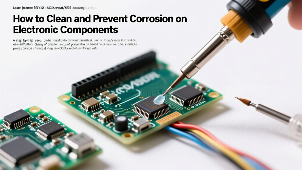
- For Galvanic & Fretting: Use 99% ACS-grade Isopropyl Alcohol (IPA) paired with an ESD-safe hog-hair brush. For stubborn fretting on gold edge connectors, apply Chemtronics DeoxIT D5 (~$18/can). DeoxIT contains oleic acid, which dissolves oxidation and leaves a protective molecular film.
- For Electrolytic Capacitor Leakage: Standard aluminum electrolytic capacitors use an alkaline borate electrolyte. If left untreated, it will dissolve the copper trace entirely. As detailed in the Electronics Notes capacitor leakage guide, you must neutralize the base. Apply a 50/50 mix of distilled white vinegar and distilled water using a cotton swab, let it react for 60 seconds, then immediately flood the area with 99% IPA to halt the reaction and displace the water.
Step 3: Ultrasonic Agitation (With Strict Caveats)
For densely populated boards where corrosion has wicked under QFN or BGA packages, manual brushing is insufficient. An ultrasonic cleaner operating at 40kHz (such as the VEVOR 3L series, ~$65 in 2026) is required.
Expert Warning: Never use 28kHz industrial cleaners on PCBs; the larger cavitation bubbles will fracture ceramic chip capacitors (MLCCs). Furthermore, you must physically remove or mask MEMS microphones, RTC tuning fork crystals (32.768kHz), and unsealed potentiometers before ultrasonic cleaning, as the acoustic resonance will permanently destroy their internal structures.
Protocol: Submerge the bare PCB in a 50/50 mix of 99% IPA and distilled water. Run for exactly 3 to 4 minutes at 40°C. Immediately follow with a pure 99% IPA rinse to displace water, then bake in a convection oven at 60°C for 4 hours.
Phase 3: Verification & Advanced Troubleshooting
Cleaning is only half the skill; verifying the integrity of the cleaned circuit is where true expertise lies. According to the IPC-A-610 Acceptability of Electronic Assemblies standard, a cleaned pad must exhibit a uniform, bright metallic finish without pitting or delamination.
Testing for Hidden Damage
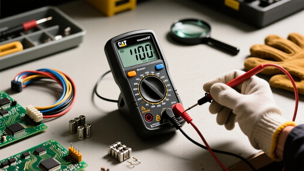
- Continuity Testing: Use a multimeter in continuity mode to check adjacent fine-pitch pins (e.g., 0.4mm pitch QFPs). Dendritic growth often leaves behind microscopic ionic paths that cause high-resistance shorts (e.g., 10kΩ instead of an open circuit) which a standard beep-test might miss. Measure resistance explicitly.
- Thermal Imaging: Power the board and use a thermal camera (like the FLIR ONE Edge Pro, ~$249). Corroded vias often suffer from internal barrel cracking, which manifests as localized hot spots due to increased resistance under load.
Phase 4: Sealing the Repair (Conformal Coating)
Once the corrosion is eradicated and the board is verified, you must alter the environment to prevent recurrence. Exposing bare, cleaned copper to ambient humidity guarantees rapid re-oxidation. Applying a conformal coating is the final, mandatory step in the skill path.
For most DIY and commercial repair scenarios, acrylic coatings are the optimal choice due to their ease of application, UV traceability, and reworkability. The MG Chemicals 419D Acrylic Conformal Coating (~$28 per liter) is an industry staple.
Application Best Practices
- Masking: Use high-temperature polyimide (Kapton) tape to mask all connectors, switches, and test points. Coating a USB-C port or PCIe slot will render it useless.
- Viscosity Control: If spraying, apply two thin coats rather than one thick coat. Thick coats trap solvents, leading to a tacky surface that attracts dust and eventually cracks during thermal cycling.
- Curing: Allow 15 minutes of flash-off time between coats. Full cure takes 24 hours at room temperature, or can be accelerated to 2 hours at 60°C.
Summary Checklist for the Technician
Mastering the management of corrosion on electronic components requires a disciplined, sequential approach. Keep this checklist at your bench:
- Diagnose the corrosion type (Galvanic, Electrolytic, Fretting, Dendritic).
- Perform dry mechanical removal of heavy crusts.
- Apply targeted chemistry (DeoxIT for fretting, weak acid neutralization for alkaline electrolyte leaks).
- Utilize 40kHz ultrasonic cleaning for BGA/QFN wicking, avoiding sensitive MEMS components.
- Bake at 60°C to eliminate trapped moisture.
- Verify with high-impedance resistance checks and thermal imaging.
- Seal with an acrylic conformal coating (e.g., MG 419D) to lock out ambient humidity.
By internalizing these specific chemical interactions and mechanical protocols, you transition from a reactive parts-swapper to a proactive reliability engineer, capable of salvaging boards that others would discard.