
The I2C Address Bottleneck: Why Migrate?
When scaling an Arduino, ESP32, or Raspberry Pi Pico project from a single environmental sensor to a distributed multi-node array, makers inevitably hit the I2C address wall. Sensors like the BME280, SHT31, or VL53L1X often have hardcoded I2C addresses or offer only a single alternative address via a hardware jumper. If your project requires three identical humidity sensors across different physical zones, standard I2C bus topologies will fail due to address collisions. Software I2C (bit-banging) is a common but unreliable workaround that consumes excessive CPU cycles and struggles with timing-sensitive sensors.
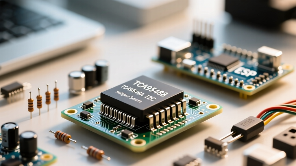
The professional migration path is upgrading your hardware architecture using a dedicated I2C switch. Specifically, integrating a tca9548a i2c multiplexer allows a single master microcontroller to route I2C traffic to up to eight independent downstream buses. This guide covers the electrical engineering considerations, hardware upgrades, and firmware refactoring required to successfully migrate your project to a multiplexed I2C topology.
TCA9548A vs. Legacy Alternatives
Before the Texas Instruments TCA9548A became the maker standard, engineers relied on the NXP PCA9548A or attempted to use analog multiplexers like the CD74HC4067. While the TCA and PCA share nearly identical pinouts and command sets, the TCA series offers distinct advantages for modern mixed-voltage microcontroller ecosystems, particularly when migrating older 5V Arduino UNO setups to 3.3V ESP32 architectures.
| Feature | TCA9548A (TI) | PCA9548A (NXP) | CD74HC4067 (Analog Mux) | Software I2C (Bit-Bang) |
|---|---|---|---|---|
| Operating Voltage | 1.65V to 5.5V | 2.3V to 5.5V | 2.0V to 6.0V | MCU Dependent |
| Channel Isolation | High (Dedicated FETs) | High (Dedicated FETs) | Poor (Analog Switch Ron) | N/A (Separate Pins) |
| Interrupt Routing | Yes (Active Low) | Yes (Active Low) | No | No |
| Bus Capacitance Handling | Excellent | Good | Degrades Signal | Highly Variable |
Voltage Translation and Logic Level Shifting
One of the primary reasons to choose the TCA9548A for a migration project is its inherent pass-gate architecture. Because the pass FETs are powered by the VCC rail, the multiplexer naturally isolates downstream capacitance. However, it is not a dedicated logic level shifter. If your MCU operates at 3.3V and a downstream sensor requires 5V logic, the TCA9548A will pass the 3.3V SDA/SCL signals directly. For mixed-voltage migrations, you must place a dedicated level shifter (like a BSS138-based breakout) on the specific downstream channel that requires 5V.
Hardware Upgrade: Wiring and Pull-Up Resistor Math
Migrating to a multiplexed bus requires careful attention to pull-up resistors. The I2C specification relies on open-drain architectures, meaning devices only pull the SDA and SCL lines LOW; resistors are required to pull them HIGH. Most commercial TCA9548A breakout boards (such as those from Adafruit) include 10kΩ pull-up resistors on the upstream bus and sometimes on the downstream channels.
The Parallel Resistance Trap
A common failure mode during hardware migration occurs when makers daisy-chain multiple sensor breakouts alongside the multiplexer. If your MCU breakout has 4.7kΩ pull-ups, your TCA9548A has 10kΩ, and your OLED display has 4.7kΩ, the equivalent parallel resistance on the upstream bus drops to approximately 1.6kΩ. According to the NXP I2C Bus Specification, the maximum allowable sink current (IOL) for a standard I2C pin is 3mA. At 3.3V, a 1.6kΩ resistor network will attempt to sink over 2mA, pushing the microcontroller's GPIO pins to their absolute limits and potentially causing logic LOW voltage (VOL) to rise above the 0.4V threshold, resulting in phantom reads and bus lockups.
Migration Action: Use a multimeter to measure the equivalent resistance between VCC and SDA on your primary bus. If it is below 2.2kΩ, physically scrape off or desolder the surface-mount pull-up resistors on the downstream sensor breakouts, leaving only the multiplexer's pull-ups active.
Firmware Migration: Refactoring Your Arduino Sketch
Transitioning your codebase to support the tca9548a i2c multiplexer requires abstracting your sensor initialization and polling routines. The multiplexer acts as a slave device on the primary bus (default address 0x70). To route traffic to a specific channel, the MCU sends a single control byte where the lower 8 bits correspond to the 8 channels.
The Channel Selection Function
Rather than initializing all sensors in the standard setup() loop simultaneously, you must wrap every I2C transaction in a channel-select command. The binary shift operator is the most efficient way to generate this byte. For example, to enable Channel 3, you write 1 << 3 (which equals 0x08). To enable Channels 0 and 4 simultaneously, you write (1 << 0) | (1 << 4).
Expert Migration Tip: Never leave multiple channels open simultaneously unless you have explicitly verified that no downstream devices share an I2C address. Leaving channels open merges their physical bus capacitance, which can easily exceed the 400pF I2C limit and corrupt data packets.
When refactoring your object-oriented sensor wrappers (e.g., Adafruit_BME280), you must pass the channel number into your read functions. The sequence must always be: Select Channel -> Request Data -> Read Data -> Deselect Channel (write 0x00 to the mux). Failing to close the channel can cause interrupt conflicts if multiple sensors use the same INT pin routed back to the MCU.
Real-World Failure Modes and Debugging
Even with perfect wiring, multiplexed I2C buses introduce new electrical physics that can break previously stable code. Understanding these failure modes is critical for a successful upgrade.
Bus Capacitance and Clock Stretching
Every FET switch inside the TCA9548A, every millimeter of copper trace, and every sensor's internal protection diode adds parasitic capacitance to the bus. The official Texas Instruments TCA9548A Datasheet notes that while the IC isolates downstream capacitance from the upstream MCU, the downstream channel itself is still bound by the 400pF limit. If you are running long CAT5 cables to remote sensors on Channel 2, the capacitance may exceed 400pF. The symptom is not a total failure, but rather corrupted ACK bits at 400kHz Fast Mode.
The Fix: In your Arduino setup, immediately after initializing the Wire library, force the bus speed down to Standard Mode by calling Wire.setClock(100000);. This gives the RC circuit formed by your pull-up resistors and parasitic capacitance enough time to charge to a valid logic HIGH before the next clock edge.
Reset Pin (RST) Handling During Brownouts
Many maker-oriented breakout boards leave the TCA9548A's active-low RST pin floating or tied high via a weak internal pull-up. In environments with motors, relays, or long power cables, voltage brownouts can cause the MCU to reset while the TCA9548A remains powered. The MCU will reboot and attempt to scan the bus, but the multiplexer may be left in an undefined state, holding a channel open or locking the SDA line low.
For a robust, production-grade migration, connect the TCA9548A RST pin to a dedicated GPIO on your microcontroller. In your firmware's setup() routine, drive this GPIO LOW for 10 milliseconds, then HIGH. This guarantees the multiplexer's internal state machine is flushed and all channels are disabled before your MCU begins its sensor initialization sequence.