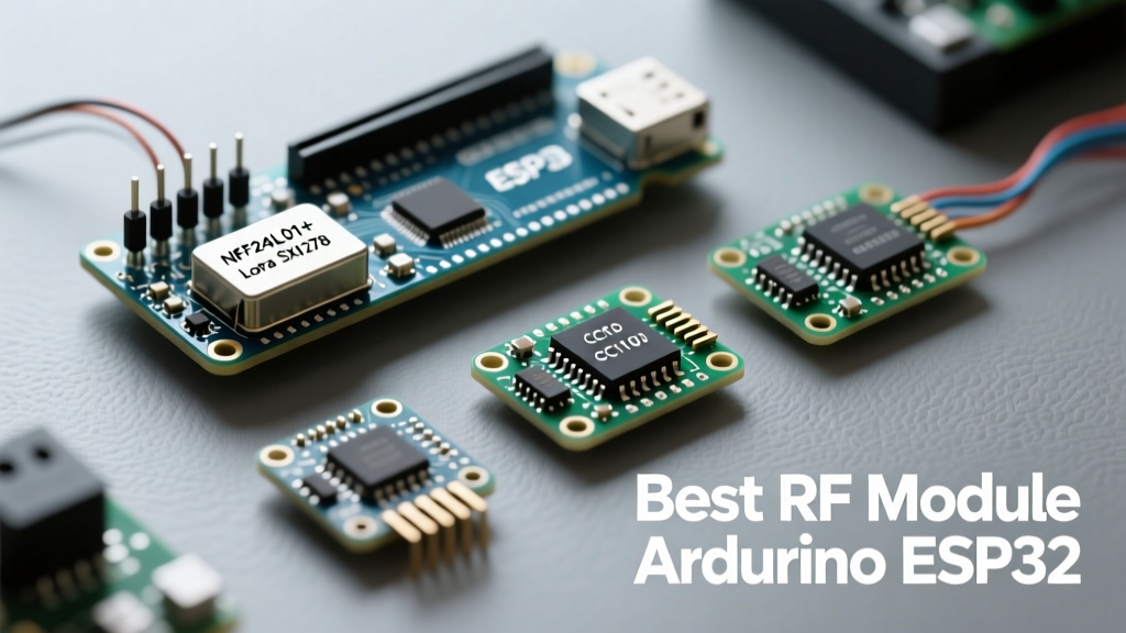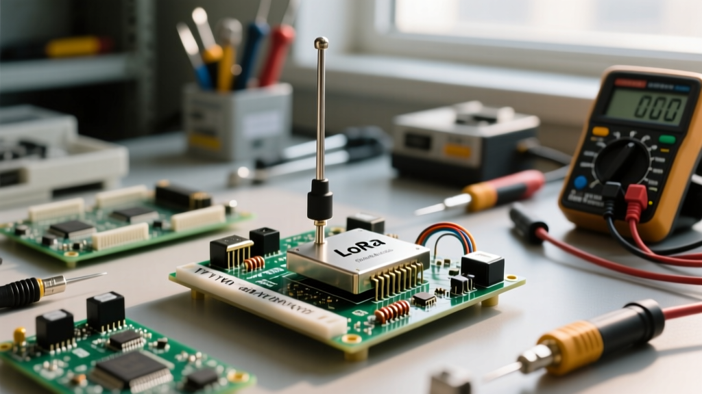

LoRa (Long Range) technology has fundamentally transformed the Internet of Things (IoT), enabling low-power, wide-area networks (LPWAN) that can transmit data over several kilometers. However, the physical layer (PHY) hardware—specifically the raw LoRa module—is highly unforgiving of electrical and RF design errors. Unlike standard Wi-Fi or Bluetooth modules that feature robust internal protection circuits, raw Sub-GHz transceivers like the Semtech SX1276 and SX1262 require strict adherence to safety and best practices.
Whether you are integrating an AI-Thinker RA-02, an Ebyte E32, or a custom PCB with a bare SX1262 chip, failing to manage impedance matching, power delivery, and logic levels will result in catastrophic silicon failure. This guide details the exact failure modes of LoRa modules and provides actionable engineering frameworks to protect your hardware.
The Silent Killer: Antenna Mismatch and VSWR Burnout
The most common cause of instant death for a LoRa module is transmitting without an antenna, or with a severely mismatched antenna. When a radio frequency (RF) power amplifier (PA) pushes energy into a transmission line, it expects a 50-ohm impedance. If the antenna is missing, broken, or poorly tuned, the energy reflects back into the module. This is measured as the Voltage Standing Wave Ratio (VSWR).
Calculating Reflected Power on SX1276 vs SX1262
A VSWR of 1:1 is perfect; all power is radiated. A VSWR of 3:1 means approximately 25% of your transmitted power is reflected back into the silicon. When you leave an antenna disconnected (an open circuit), the VSWR approaches infinity, and 100% of the RF energy is reflected.
- SX1276 / SX1278: Capable of outputting up to +20dBm (100mW). If transmitted into an open circuit, the internal PA stage overheats and destroys the output matching network in milliseconds.
- SX1262: A newer, more efficient chip capable of +22dBm (158mW). While it features some internal over-current protection, sustained transmission into a high-VSWR load will still permanently degrade the PA efficiency or fry the die.
Never initiate a TX (transmit) command via SPI without a verified 50-ohm load attached to the RF output. If you must test firmware without an antenna, you must use a 50-ohm SMA dummy load or reduce the TX power to the absolute minimum (e.g., -9dBm) via the software registers.
Mechanical Stress on u.FL and SMA Pigtails
Many compact LoRa modules utilize IPEX/U.FL connectors for the antenna. These connectors are rated for a maximum of 30 mating cycles and are highly susceptible to mechanical stress. Bending the SMA pigtail cable sharply near the U.FL crimp can cause an internal short or an impedance discontinuity, leading to localized VSWR spikes that degrade range and stress the PA. Always secure the pigtail cable with Kapton tape or a 3D-printed strain relief bracket to prevent the U.FL connector from being ripped from the PCB pads.
Power Delivery: Decoupling and Brownout Prevention
LoRa modules exhibit extreme current transients. When transitioning from sleep mode to a high-power TX burst, the current draw spikes from under 1µA to over 120mA in a matter of microseconds. If your power supply cannot respond to this transient demand, the VCC rail will droop.
The 100nF and 10µF Rule for LoRa Transceivers
If the VCC rail drops below the brownout threshold (typically around 2.4V to 2.7V depending on the chip), the internal state machine of the LoRa module will corrupt. The SPI bus will latch up, and the microcontroller will be unable to reset the module without a hard physical power cycle. To prevent this, you must implement a strict decoupling network:
- 100nF (0.1µF) MLCC Capacitor: Must be placed as close to the VCC and GND pins of the LoRa module as physically possible (within 2mm). This handles the high-frequency transient spikes.
- 10µF to 47µF Tantalum or MLCC Capacitor: Placed near the module to act as a local energy reservoir, sustaining the 120mA draw during the initial TX ramp-up before the main voltage regulator can react.
Do not rely on the output capacitor of your main 3.3V LDO (like an AMS1117) if it is located more than a few centimeters away from the LoRa module. Trace inductance will choke the transient current, guaranteeing a brownout.
Logic Level Translation: The 5V Arduino Trap
A fatal mistake made by beginners is connecting a 5V microcontroller directly to a 3.3V LoRa module. The Semtech SX127x and SX126x families operate strictly on 3.3V logic. The SPI pins (MOSI, MISO, SCK, NSS) and GPIO pins (DIO0, DIO1, RESET) are not 5V tolerant.
Feeding 5V from an ATmega328P (Arduino Uno/Nano) into the MISO or MOSI pins will forward-bias the internal ESD protection diodes. This injects current directly into the VCC rail, potentially causing phantom powering, logic corruption, and eventual thermal destruction of the GPIO silicon. To interface a 5V MCU with a LoRa module safely, you must use a logic level shifter. The CD4050 non-inverting buffer or a BSS138 MOSFET-based bidirectional level shifter are the industry standards for this task. Alternatively, migrate your design to a native 3.3V microcontroller like the STM32, ESP32, or SAMD21.
Electrostatic Discharge (ESD) and GPIO Protection
The RF antenna pin is directly exposed to the outside world, making it a prime target for Electrostatic Discharge (ESD). A static shock from a human finger (which can easily exceed 3,000V) traveling down the antenna and into the U.FL connector will instantly puncture the gate oxide of the internal Low Noise Amplifier (LNA), destroying the receiver's sensitivity.
When designing a custom PCB or modifying a breakout board, integrate a TVS (Transient Voltage Suppression) diode specifically rated for RF lines. Components like the PESD0402-140 offer ultra-low capacitance (under 0.2pF), ensuring they do not detune your 50-ohm impedance matching network while safely shunting ESD strikes to ground.
Comparative Hardware Safety Matrix
Understanding the specific limits of your chosen LoRa module is critical for designing safe driver circuits. Below is a comparison of popular modules and their electrical tolerances.
| Module / Chip | Max TX Current | VCC Tolerance | Logic Level | Common Failure Mode |
|---|---|---|---|---|
| SX1276 (RA-02) | 120mA (+20dBm) | 1.8V - 3.7V | 3.3V Strict | PA burnout from open antenna |
| SX1262 (Ebyte E22) | 140mA (+22dBm) | 1.8V - 3.7V | 3.3V Strict | SPI latch-up from VCC brownout |
| Ebyte E32-433T30D | 750mA (+30dBm) | 3.0V - 5.2V | 3.3V / 5V Tol. | Thermal shutdown from high duty cycle |
Note: The Ebyte E32 series includes an onboard MCU and external PA/LNA, which changes the power profile and logic tolerance compared to raw Semtech chips.
Regulatory Compliance and RF Exposure Safety
Safety extends beyond protecting the hardware; it also involves complying with regional RF spectrum regulations to avoid interfering with critical infrastructure and adhering to human exposure limits.
ISM Band Duty Cycle Limits (868MHz vs 915MHz)
LoRa operates in unlicensed ISM (Industrial, Scientific, and Medical) bands, but 'unlicensed' does not mean 'unregulated'. In Europe (868MHz), the ETSI mandates strict duty cycle limits, typically 1% per sub-band. This means if you transmit a packet that takes 1 second of airtime, the LoRa module must remain silent for 99 seconds on that specific frequency. Failing to implement duty-cycle tracking in your firmware can result in your device being flagged and blocked by network gateways like The Things Network (TTN).
In the United States (915MHz), the FCC regulates maximum conducted power and requires frequency hopping (LBT/FHSS) to distribute the RF energy across the spectrum. Furthermore, while LoRa is low power, utilizing high-gain directional Yagi antennas can concentrate the RF field. Builders should consult the ARRL RF Safety Guidelines to ensure their setup remains within safe Specific Absorption Rate (SAR) limits for human exposure, particularly when mounting antennas on vehicles or residential roofs.
Secure Boot and Firmware Safety
Finally, from a cybersecurity and operational safety perspective, ensure your SPI communication lines are protected from noise. In industrial environments with heavy motors or relays, electromagnetic interference (EMI) can induce voltage spikes on the SPI MISO/MOSI lines, causing the microcontroller to send corrupted register configurations to the Semtech SX1276. This can accidentally command the module to transmit on restricted frequencies or at maximum duty cycle, violating local laws. Always use shielded SPI cables or route SPI traces over a solid ground plane on your PCB to maintain signal integrity.