
The Atomic Root: Band Theory and Electron Mobility
When troubleshooting a short circuit, designing a custom wire harness, or simply sizing a branch circuit, understanding the fundamental difference between an insulator and a conductor is the absolute baseline for electrical safety and efficiency. While most DIYers and junior electricians know that copper carries current and plastic stops it, the actual physics governing these materials dictate how every wire in your home or industrial facility behaves under stress, heat, and age.
At the atomic level, the distinction comes down to band theory. In solid-state physics, electrons occupy specific energy levels. The valence band contains the electrons bound to atoms, while the conduction band contains the free electrons that facilitate electrical flow. According to HyperPhysics at Georgia State University, the primary difference between an insulator and a conductor lies in the 'band gap'—the energy void between these two bands.
- Conductors (e.g., Copper, Aluminum, Silver): The valence and conduction bands overlap. There is effectively zero band gap. Even at room temperature, thermal energy is enough to push vast quantities of electrons into the conduction band, allowing them to drift freely when a voltage is applied.
- Insulators (e.g., PVC, XLPE, Teflon, Glass): The band gap is massive (typically greater than 5 electron volts). Electrons are tightly bound in covalent or ionic bonds. Standard electrical voltages (120V to 480V) cannot provide the energy required to bridge this gap, effectively trapping the electrons and preventing current flow.
Head-to-Head Material Comparison Matrix
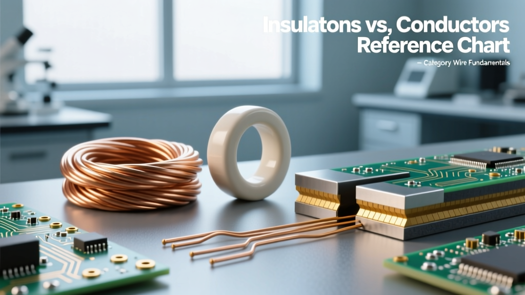
To truly grasp the operational differences, we must look at the quantitative metrics that electrical engineers use when specifying wire types like THHN or XHHW-2. The table below contrasts a standard conductor with two of the most common insulating polymers used in modern electrical wiring.
| Property | Conductor (Copper) | Insulator (PVC) | Insulator (XLPE) |
|---|---|---|---|
| Resistivity (Ω·m) | ~1.68 x 10^-8 | >10^14 | >10^15 |
| Band Gap (eV) | 0 (Overlapping) | ~5.0 - 8.0 | ~8.0+ |
| Temp Coefficient | Positive | Negative | Negative |
| Dielectric Strength | N/A | ~10-15 kV/mm | ~20-30 kV/mm |
| Max Operating Temp | 1083°C (Melting) | 75°C - 105°C | 90°C - 105°C |
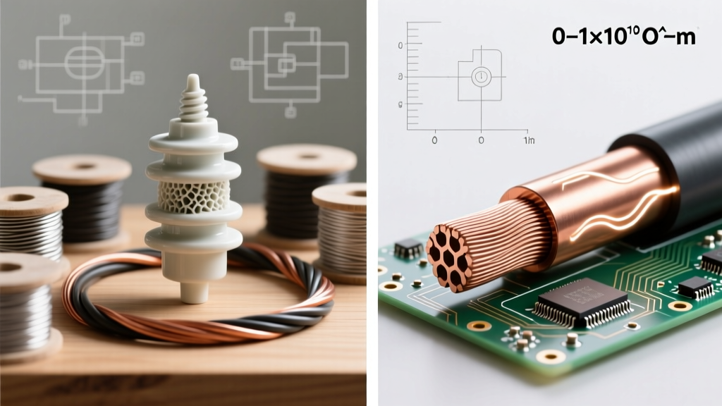
Notice the resistivity difference. Copper’s resistivity is measured in fractions of a micro-ohm, while PVC and Cross-Linked Polyethylene (XLPE) are measured in hundreds of trillions of ohms. This 22-order-of-magnitude gap is what makes modern electrical distribution possible.
The Thermal Inversion: How Heat Changes the Rules
One of the most critical, yet frequently misunderstood, aspects of wire fundamentals is how temperature affects these two material classes in completely opposite ways. This phenomenon is known as the thermal inversion of resistance.
Conductors: The Positive Temperature Coefficient
As a copper or aluminum conductor heats up (due to ambient temperature or I²R heating from high current), the metal's atomic lattice vibrates more violently. These vibrations scatter the free-flowing electrons, increasing collisions. Therefore, as temperature rises, a conductor's resistance increases. This is why the National Electrical Code (NEC) mandates ampacity derating for conductors installed in hot environments, like attics or near boilers.
Insulators: The Negative Temperature Coefficient
Insulators behave inversely. As an insulating jacket like PVC or rubber gets hotter, the thermal energy actually helps a small number of bound electrons jump the band gap. Therefore, as temperature rises, an insulator's resistance decreases. This leads to 'leakage current'—a tiny, often imperceptible flow of current through the insulation itself. Over time, sustained high temperatures degrade the polymer chains, accelerating this leakage and eventually leading to insulation failure.
Pro Electrician Insight: Never assume that because a wire's copper core can handle 100 amps, the insulation can survive the resulting heat. The copper won't melt until 1083°C, but standard PVC insulation will become brittle, crack, and fail catastrophically at just 105°C. The insulator is almost always the weakest link in a wire's lifespan.
Dielectric Breakdown: When Insulators Become Conductors
The difference between an insulator and a conductor is not an absolute, unbreakable law; it is a threshold. If you apply enough voltage across an insulator, you will force electrons across the band gap in a violent event known as dielectric breakdown or avalanche breakdown.
When the electric field exceeds the material's dielectric strength (measured in kilovolts per millimeter, kV/mm), the insulator violently tears its own atomic bonds apart to conduct electricity. This results in an arc flash, a short circuit, and usually a fire. For context, Encyclopedia Britannica notes that dry air has a dielectric strength of roughly 3 kV/mm. High-quality XLPE insulation used in industrial medium-voltage cables can withstand 20 to 30 kV/mm. However, physical damage, moisture ingress, or chemical corrosion can create micro-fissures in the insulation, creating localized weak points where partial discharge begins long before a full breakdown occurs.
Field Testing: Verifying Insulation Integrity with a Megger
Because visual inspection cannot reveal the internal atomic degradation of an insulator, electrical professionals rely on Insulation Resistance Testers (commonly known by the brand name Megger). As outlined in Fluke's technical guides on insulation testing, a standard multimeter applies only a few volts, which is useless for checking high-resistance insulation.
A Megger applies high-voltage DC (typically 500V or 1000V) to stress the insulation and measure the micro-amp leakage current. Here is a standard framework for testing 600V-rated THHN wire:
- Isolate the Circuit: Disconnect the wire from all sensitive electronics, VFDs, and breakers. The high DC voltage will destroy solid-state components.
- Apply Test Voltage: Connect the Megger's positive lead to the copper conductor and the negative lead to the grounding system or adjacent neutral wire.
- Read the Resistance: Apply 500V DC for 60 seconds. The historical 'rule of thumb' is 1 Megohm per 1000V of operating voltage. However, for newly installed, pristine THHN wire, you should expect readings in the hundreds or thousands of Megohms (often maxing out the meter's display).
- Interpret the Results: A reading below 1 Megohm indicates severe insulation degradation, moisture intrusion, or physical puncture. The wire must be replaced immediately.
Selecting the Right Pairing for Your Application
Ultimately, mastering the difference between an insulator and a conductor allows you to select the correct wire pairing for specific environmental hazards. The conductor dictates the ampacity (current-carrying capacity), while the insulator dictates the environmental survivability.
- Standard Indoor Branch Circuits: Copper conductor with PVC insulation and a Nylon jacket (THHN). The nylon provides mechanical protection against abrasion during pulling, while the PVC provides the primary dielectric barrier.
- Wet Locations and Direct Burial: Copper or Aluminum with XLPE insulation (XHHW-2). XLPE's cross-linked molecular structure prevents water treeing and offers vastly superior dielectric strength in damp environments compared to standard thermoplastics.
- High-Temperature Industrial Ovens: Nickel-plated copper conductors paired with PTFE (Teflon) or fiberglass braided insulation. These specialized insulators maintain their massive band gaps even when exposed to sustained temperatures exceeding 200°C.
By respecting the atomic boundaries that define these materials, you ensure that your electrical systems remain safe, efficient, and compliant with rigorous modern codes.