
The Atomic Divide: Valence Electrons and Band Theory
Understanding the fundamental difference between conductors and insulators is the bedrock of all electrical engineering and DIY electronics. At the atomic level, the distinction comes down to band theory and the mobility of valence electrons. In conductive materials, the valence band (where electrons reside) and the conduction band (where electrons can move freely) overlap. This allows electrons to flow effortlessly when a voltage is applied. In insulators, a massive 'band gap' exists between these two states, requiring immense energy to force an electron into the conduction band.
For DIYers, hobbyists, and professional electricians, selecting the right materials isn't just about textbook physics; it is about managing heat, preventing dielectric breakdown, and ensuring long-term reliability in circuits. Below, we break down the most critical insulator conductor examples used in modern wiring, microcontrollers, and high-voltage applications.
Top Conductor Examples Ranked by Conductivity
When designing a circuit or sizing a wire for a subpanel, you are almost always choosing from a shortlist of highly conductive metals. The standard metric for evaluating these materials is electrical resistivity, measured in nano-ohm meters (nΩ·m) at 20°C. According to data from The Engineering Toolbox, lower resistivity equates to higher conductivity.
| Material | Resistivity (nΩ·m at 20°C) | Temp Coefficient (per °C) | Primary Real-World Application |
|---|---|---|---|
| Silver | 15.9 | 0.0038 | High-end audio contacts, RF shielding, specialized relays |
| Copper (Annealed) | 17.2 | 0.0039 | Standard house wiring (ROMEX), PCB traces, motor windings |
| Gold | 24.4 | 0.0034 | Corrosion-resistant edge connectors, IC bonding wires |
| Aluminum | 28.2 | 0.0043 | High-voltage transmission lines, large feeder cables |
The Copper Standard: C11000 ETP in DIY Electronics
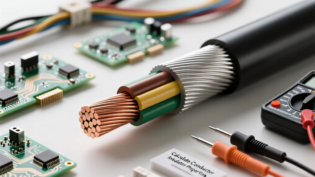
While silver is technically the most conductive metal, copper is the undisputed king of practical electrical work. Specifically, Electrolytic Tough Pitch (ETP) copper, designated as C11000, is the industry standard. It contains a minimum of 99.90% copper and a controlled amount of oxygen (around 0.02% to 0.04%). This specific oxygen level prevents hydrogen embrittlement when the wire is soldered or annealed at high temperatures. When you buy standard THHN stranded wire or solid-core breadboard jumper wires, you are almost certainly working with C11000 ETP copper. Its predictable resistance and excellent solderability make it the default choice for 95% of all low-voltage and mains-voltage DIY projects.
Aluminum Wiring: AA-8000 Series and Oxidation Realities
Aluminum is significantly lighter and cheaper than copper, making it ideal for long-distance transmission and heavy feeder wires (like 2/0 AWG for a 200-amp residential service). However, pure aluminum suffers from thermal expansion and oxidation issues. Modern electrical codes mandate the use of AA-8000 series aluminum alloys for branch circuit wiring. These alloys incorporate trace amounts of iron and other metals to increase creep resistance and tensile strength. If you are terminating aluminum wire in a DIY subpanel, you must use an anti-oxidant paste (like Noalox) and torque the lugs to the manufacturer's exact specifications to prevent high-resistance arcing faults.
Critical Insulator Examples for High and Low Voltage
An insulator's primary job is to confine the electrical current to its intended path. The effectiveness of an insulator is measured by its dielectric strength—the maximum electric field it can withstand before breaking down and becoming conductive, typically measured in kilovolts per millimeter (kV/mm). As noted by Georgia State University's HyperPhysics database, the atomic structure of these materials tightly binds their electrons, resisting current flow.
| Insulation Material | Dielectric Strength (kV/mm) | Max Operating Temp | Common Electrical Application |
|---|---|---|---|
| Air (at 1 atm) | ~3.0 | N/A | Overhead transmission line spacing, relay contacts |
| PVC (Polyvinyl Chloride) | 15 - 40 | 75°C to 105°C | Standard THHN wire jacketing, cheap cable sleeving |
| XLPE (Cross-Linked Polyethylene) | 20 - 50 | 90°C to 150°C | XHHW-2 wire, underground direct-burial cables |
| PTFE (Teflon) | 60 - 100+ | 260°C | Aerospace wiring, high-frequency RF coaxial cables |
| Mica | 100 - 150 | 500°C+ | High-temperature heating elements, vintage capacitors |
PVC vs. XLPE: Choosing the Right Jacket for Mains Wiring
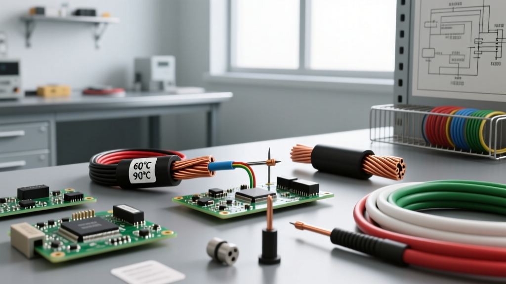
In residential and commercial wiring, you will frequently encounter THHN and XHHW-2 wire designations. THHN uses a PVC insulation layer with a nylon outer jacket. While PVC is cheap and flexible, it emits toxic hydrochloric acid gas when burned and becomes brittle under prolonged UV exposure. XHHW-2, on the other hand, uses Cross-Linked Polyethylene (XLPE). The cross-linking process creates a 3D molecular mesh that drastically improves thermal stability and moisture resistance. For DIYers running conduit in wet locations (like underground PVC to a detached garage or a well pump), XHHW-2 is vastly superior to THHN.
PTFE (Teflon) and High-Frequency RF Applications
When designing microcontroller circuits that involve high-frequency RF signals (like 2.4 GHz Wi-Fi or 5 GHz radar modules), the insulator used in your coaxial cables and PCB substrates matters immensely. PTFE (Teflon) has an exceptionally low dielectric constant and low dissipation factor. This means it does not absorb or distort high-frequency electromagnetic waves. While standard FR-4 fiberglass PCBs are fine for digital logic and DC power, RF engineers rely on PTFE-based laminates (like Rogers RO4003C) to maintain signal integrity in high-speed digital and radio-frequency designs.
Semiconductors: Bridging the Gap in Microcontrollers
No discussion of insulator conductor examples is complete without addressing the materials that sit exactly between them: semiconductors. Materials like Silicon (Si) and Germanium (Ge) have a moderate band gap. In their pure, intrinsic state, they act mostly as insulators. However, through a process called 'doping'—introducing trace amounts of elements like phosphorus (n-type) or boron (p-type)—their conductivity can be precisely controlled. This ability to switch between acting as an insulator and a conductor via an applied voltage is the foundational mechanism of the MOSFETs and logic gates inside every Arduino, ESP32, and STM32 microcontroller you program.
Real-World Failure Modes: When Insulators Break Down
Insulators are not perfect; they have strict operational limits. Understanding how insulators fail is critical for troubleshooting and safe DIY design.
- Dielectric Breakdown: If the voltage exceeds the material's dielectric strength, electrons are violently ripped from their atoms, creating a conductive plasma channel. This is how lightning travels through the air, and how overvoltage spikes can permanently puncture the thin silicon dioxide insulating layer inside a MOSFET, destroying the component.
- Electrical Tracking (Carbonization): Organic insulators like PVC, wood, or paper can degrade over time when exposed to surface arcing and moisture. The heat from micro-arcs burns the carbon-hydrogen bonds, leaving behind a trail of pure carbon. Since carbon is a conductor, this 'track' eventually bridges the gap between live and neutral, causing a dead short or fire.
- Thermal Degradation: Pushing too much current through a wire generates I²R heat. If a 14 AWG wire is pushed beyond its ampacity, the PVC insulation will soften, melt, and eventually catch fire, completely eliminating the insulating barrier.
Expert Safety Note: Never rely on standard electrical tape (like vinyl PVC tape) as a primary insulator for high-voltage or high-heat splices. Over time, the adhesive dries out, and the tape unspools. For permanent, high-reliability DIY splices, use adhesive-lined heat shrink tubing with a 3:1 shrink ratio and an inner layer of thermoplastic adhesive that melts to form a waterproof, structural seal.
By mastering the properties of these insulator conductor examples, you can make informed decisions about wire sizing, PCB layout, and component selection. Whether you are selecting C11000 copper for a custom motor winding or specifying XLPE insulation for an outdoor solar array, respecting the atomic realities of these materials is the key to building safe, efficient, and lasting electrical systems. For further reading on insulation safety standards and dielectric testing protocols, refer to the resources provided by Underwriters Laboratories (UL).