
When beginners search for what is an insulator electricity basics, they are usually met with a simplistic definition: a material that blocks the flow of electrons. However, in professional electrical engineering, wire sizing, and high-voltage system design, an insulator is not merely a passive barrier. It is a complex dielectric medium governed by strict mathematical limits, thermal constraints, and electromagnetic field distributions. Understanding what an insulator in electricity truly is requires moving beyond basic definitions and diving into dielectric strength calculations, insulation resistance formulas, and material degradation physics.
The Quantum Reality: Band Gap Theory
To understand the fundamental physics of an electrical insulator, we must look at the atomic level. In solid-state physics, materials are classified by their electronic band structure—specifically, the energy gap (band gap) between the valence band (where electrons are bound to atoms) and the conduction band (where electrons are free to move and conduct current).
- Conductors (e.g., Copper, Aluminum): The valence and conduction bands overlap. Electrons move freely with minimal energy input.
- Semiconductors (e.g., Silicon): A small band gap exists (typically 1 to 3 eV). Thermal energy or doping can excite electrons into the conduction band.
- Insulators (e.g., PTFE, XLPE, Mica): A massive band gap exists, typically greater than 5 eV. Under normal operating voltages, electrons cannot bridge this gap, resulting in near-zero conductivity.
According to Georgia State University's HyperPhysics, it is this wide forbidden energy gap that gives insulators their incredibly high volume resistivity, often exceeding $10^{14}$ ohm-meters.
Dielectric Strength vs. Insulation Resistance: The Math
When sizing wire insulation or designing busbar supports, engineers must evaluate two distinct but equally critical properties: Dielectric Strength and Insulation Resistance. Confusing the two is a common cause of catastrophic field failures.
Formula 1: Calculating Breakdown Voltage (Dielectric Strength)
Dielectric strength measures the maximum electric field an insulating material can withstand before it breaks down and becomes conductive. It is typically expressed in kilovolts per millimeter (kV/mm). The theoretical breakdown voltage ($V_b$) is calculated as:
$V_b = E_d \times t$
Where:
$V_b$ = Breakdown Voltage (kV)
$E_d$ = Dielectric Strength of the material (kV/mm)
$t$ = Thickness of the insulation (mm)
Real-World Application: If you are using cross-linked polyethylene (XLPE) with a dielectric strength of 25 kV/mm, and your wire insulation thickness is 2.0 mm, the theoretical breakdown voltage is 50 kV. However, per IEC 60243 standards, engineers must apply a safety factor (typically 3x to 5x) to account for manufacturing voids, thermal aging, and transient voltage spikes.
Formula 2: Insulation Resistance and Leakage Current
While dielectric strength deals with catastrophic failure, insulation resistance deals with continuous, microscopic leakage currents. For a cylindrical wire conductor, the insulation resistance ($R_i$) is not a simple linear calculation because the electric field radiates outward. The formula is:
$R_i = \frac{\rho}{2 \pi L} \ln(\frac{D}{d})$
Where:
$\rho$ = Volume resistivity of the insulator ($\Omega\cdot m$)
$L$ = Length of the cable (m)
$D$ = Outer diameter of the insulation (m)
$d$ = Inner diameter (conductor diameter) (m)
This logarithmic relationship reveals a critical design insight: doubling the insulation thickness does not double the insulation resistance. After a certain thickness, adding more insulation yields diminishing returns for leakage current prevention, making material selection (higher $\rho$) far more important than sheer bulk.
Material Comparison Chart: Dielectric Properties
Selecting the right insulator requires balancing electrical limits with thermal and mechanical constraints. Below is a comparison of common electrical insulators used in wire manufacturing and high-voltage applications.
| Material | Dielectric Constant ($k$) | Dielectric Strength (kV/mm) | Volume Resistivity ($\Omega\cdot m$) | Max Continuous Temp |
|---|---|---|---|---|
| PVC (Polyvinyl Chloride) | 3.0 - 4.0 | 15 - 40 | $10^{12}$ | 70°C - 105°C |
| XLPE (Cross-Linked PE) | 2.3 | 20 - 50 | $10^{14}$ | 90°C |
| PTFE (Teflon) | 2.1 | 60 - 100 | $10^{18}$ | 260°C |
| Mica (Glass-Bonded) | 5.0 - 7.0 | 100 - 200 | $10^{15}$ | 500°C+ |
| EPDM Rubber | 2.5 - 3.5 | 25 - 35 | $10^{13}$ | 90°C - 150°C |
Note on Dielectric Constant ($k$): In high-frequency applications or Variable Frequency Drive (VFD) cables, a lower dielectric constant is highly desirable. A lower $k$ reduces the parasitic capacitance between the conductor and the ground plane, minimizing charging currents and signal distortion.
Calculation Tutorial: Sizing a 15kV DC Busbar Insulator
Let us apply these concepts to a practical calculation tutorial. Suppose you are designing a custom 15kV DC busbar for an industrial traction motor drive, and you need to size the PTFE stand-off insulators.
- Identify the Peak Voltage: The nominal voltage is 15kV DC. Accounting for switching transients and inductive kickback, we design for a peak voltage ($V_{peak}$) of 18kV.
- Select the Material: We choose PTFE due to its high thermal stability and exceptional volume resistivity. Its rated dielectric strength ($E_d$) is conservatively taken as 60 kV/mm.
- Apply the Safety Factor: For critical high-voltage DC infrastructure, NEMA standards and best practices dictate a minimum safety factor of 4.0 to prevent partial discharge inception over the 20-year lifespan of the equipment.
- Calculate Minimum Thickness:
$Design\ Strength = \frac{60\ kV/mm}{4.0} = 15\ kV/mm$
$t = \frac{V_{peak}}{Design\ Strength} = \frac{18\ kV}{15\ kV/mm} = 1.2\ mm$ - Mechanical Override: While 1.2 mm is the electrical minimum, the busbar weighs 45 kg and experiences vibrational stress. Mechanical shear calculations dictate a minimum cross-sectional area requiring a physical thickness of 25 mm. In this scenario, mechanical requirements vastly exceed the electrical breakdown threshold, ensuring extreme dielectric safety.
Real-World Failure Modes: When the Math Fails
Even if your calculations are flawless, insulators fail in the field. Understanding these failure modes is crucial for troubleshooting and preventative maintenance.
1. Partial Discharge (PD) and Corona
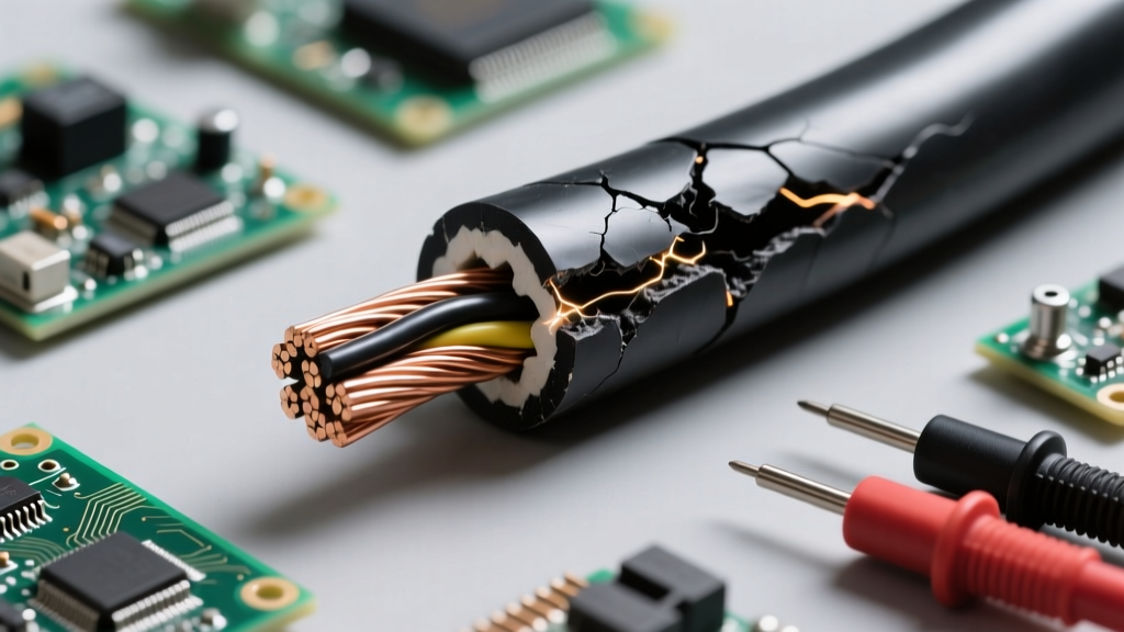
If microscopic air voids are trapped inside solid insulation (like epoxy or XLPE) during manufacturing, the air inside the void has a much lower dielectric strength (approx. 3 kV/mm) than the surrounding solid material. Under high voltage, the air in the void ionizes, creating a localized micro-spark known as partial discharge. Over time, this PD erodes the surrounding solid insulation, creating conductive carbonized 'trees' (electrical treeing) that eventually bridge the gap and cause a catastrophic short circuit.
2. Surface Tracking
Insulation resistance calculations assume a pristine surface. In reality, industrial environments deposit dust, moisture, and conductive salts on the exterior of insulators. This creates a conductive path along the surface of the material, bypassing the internal dielectric strength entirely. To combat this, engineers use 'creepage distance' calculations, adding physical ribs or sheds to the insulator to force the surface current to travel a longer, more resistive path.
3. Thermal Degradation (The Arrhenius Effect)
Insulators do not last forever when subjected to heat. The lifespan of an insulator is modeled using the Arrhenius equation, which dictates that for every 8°C to 10°C increase in operating temperature above the material's rated limit, the chemical lifespan of the polymer insulation is cut in half. A wire rated for 90°C operating continuously at 110°C will experience severe embrittlement and dielectric loss in a fraction of its expected service life.
Summary & Best Practices
Answering the question of what an insulator in electricity is requires a multidisciplinary approach. It is a material defined by its quantum band gap, quantified by its dielectric strength and volume resistivity, and limited by its thermal and mechanical environment. When sizing wire insulation or designing high-voltage barriers, always calculate both the theoretical breakdown voltage and the continuous leakage resistance. Apply rigorous safety factors for transient spikes, prioritize creepage distance in dirty environments, and never exceed the thermal limits of your chosen dielectric material.