
Decoding the Potentiometer: Anatomy and Terminals
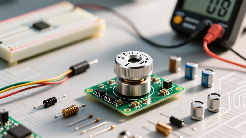
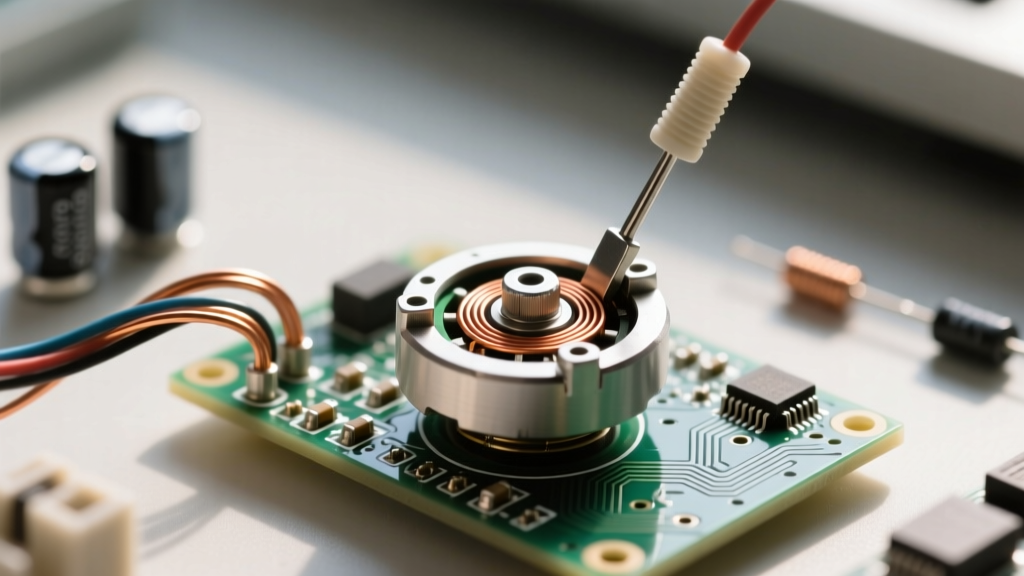
Before you can successfully integrate a variable resistor into your circuit, you must first understand its physical anatomy. A potentiometer (often called a "pot") is fundamentally a three-terminal resistor with a sliding or rotating contact that forms an adjustable voltage divider. When you turn the shaft, you are moving a metallic or carbon wiper across a resistive track. This mechanical action alters the resistance between the wiper and the outer terminals, allowing you to manually control voltage or current.
For hobbyists and engineers alike, the most common point of failure when learning how to hook up a potentiometer is misidentifying the pins. Unlike polarized components like electrolytic capacitors or LEDs, the outer pins of a standard potentiometer are symmetrical. The center pin is universally the wiper. However, determining which outer pin corresponds to clockwise (CW) or counter-clockwise (CCW) rotation requires either a datasheet, physical testing with a multimeter, or an understanding of standard industry pinouts.
The Taper Trap: Identifying Linear vs. Logarithmic Markings
Component identification goes far beyond simply reading the resistance value (e.g., 10kΩ). You must also identify the taper—the mathematical relationship between the shaft's physical position and the resulting resistance. Hooking up an audio-taper pot to an Arduino analog input will yield frustratingly non-linear sensor data, while using a linear pot in a volume control circuit will cause the audio to jump abruptly at the end of the rotation.
Reading the Alphanumeric Markings
Most potentiometers have their resistance and taper stamped directly onto the metal casing or molded into the plastic. However, regional manufacturing differences create a massive trap for DIYers sourcing parts globally.
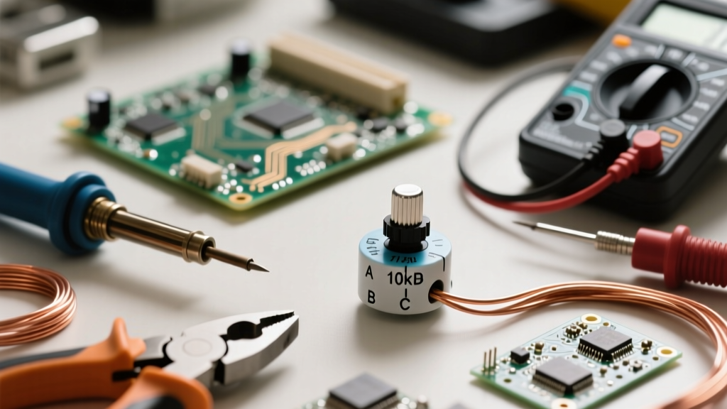
- Asian/European Standard: 'B' denotes Linear (e.g., B10K). 'A' denotes Logarithmic/Audio (e.g., A50K).
- US Standard: 'A' denotes Linear. 'B' denotes Logarithmic/Audio.
- Anti-Log/Reverse-Audio: Usually denoted by 'C' or 'F', depending on the manufacturer.
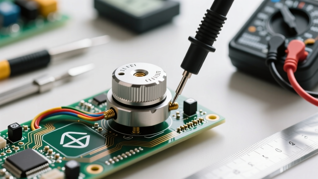
According to the comprehensive guides on Electronics Tutorials, if you are unsure of the taper, you can identify it using a multimeter. Set your meter to measure resistance, place the probes on the wiper and one outer pin, and rotate the shaft to the exact 50% mechanical midpoint. If the resistance reads exactly half of the total rated value (e.g., 5kΩ on a 10kΩ pot), it is linear. If it reads significantly higher or lower (e.g., 1.5kΩ or 8.5kΩ), it is logarithmic.
Step-by-Step: How to Hook Up a Potentiometer as a Voltage Divider
The most common application for a potentiometer in prototyping is as a voltage divider, particularly for feeding analog signals into microcontrollers like the Arduino, ESP32, or STM32. In this configuration, you are not using the pot to limit current; you are using it to output a variable voltage between 0V and your logic level (usually 3.3V or 5V).
- Pin 1 (CCW): Connect to Ground (GND).
- Pin 3 (CW): Connect to your reference voltage (e.g., 5V or 3.3V). Note: Swapping Pin 1 and Pin 3 will simply reverse the logical direction of the dial, which is easily fixed in software.
- Pin 2 (Wiper): Connect to your microcontroller's Analog-to-Digital Converter (ADC) input pin.
As detailed in the Arduino Analog Input Documentation, the ADC reads the voltage at the wiper. The mathematical formula governing this is Vout = Vin × (R2 / (R1 + R2)), where R1 is the resistance between the VCC pin and the wiper, and R2 is the resistance between the wiper and GND. For a smooth ADC reading, a 10kΩ (B10K) linear potentiometer is the industry standard, as it draws minimal current (0.5mA at 5V) while maintaining a low enough impedance to charge the microcontroller's internal sample-and-hold capacitor quickly.
Rheostat Configuration: Variable Resistance Wiring
Sometimes, you do not need a voltage divider; you need a variable resistor to control current, such as dimming a high-power LED or setting the threshold on a 555 timer circuit. This requires wiring the potentiometer as a rheostat.
To do this, you only use two pins: the wiper (Pin 2) and one outer pin (Pin 1 or 3). However, expert circuit design dictates a critical best practice: always tie the unused outer pin directly to the wiper pin. According to All About Circuits, if the wiper lifts off the resistive track due to vibration, dirt, or mechanical wear, a two-pin floating configuration will result in an open circuit (infinite resistance), potentially destroying sensitive downstream components or causing a microcontroller pin to float. By tying the wiper to the outer terminal, a wiper failure simply defaults the component to its maximum rated resistance, keeping the circuit closed and safe.
Diagnosing Common Wiring and Component Failures
Even when you know exactly how to hook up a potentiometer, physical component degradation can ruin your build. Here is a diagnostic framework for common potentiometer failures:
- Scratchy Audio or Noisy ADC Readings: This is caused by carbon dust buildup or oxidation on the resistive track. Fix: Inject a small amount of DeoxIT or contact cleaner into the casing slot and rotate the shaft back and forth 50 times.
- Dead Zones (No Change in Resistance): If a section of the rotation yields no change in voltage, the wiper has physically worn away the carbon or cermet track in that specific area. The component must be replaced.
- Reversed Logic in Software: Turning the knob clockwise decreases your value instead of increasing it. Fix: You have wired VCC to the CCW terminal. Either swap the outer wires physically, or invert the value in your code (e.g.,
1023 - analogRead()).
Prototyping Selection Matrix: Trimpots vs. Panel Mounts
Choosing the right physical form factor is just as important as the electrical pinout. Below is a comparison chart to help you select the correct component for your specific prototyping phase.
| Form Factor | Typical Use Case | Lifespan (Cycles) | Average Pricing (2025) | Example Part Number |
|---|---|---|---|---|
| Trimpot (e.g., 3386P) | PCB calibration, set-and-forget thresholds | ~200 cycles | $0.40 - $0.80 | Bourns 3386P-1-103LF |
| Panel Mount Rotary | User interfaces, audio volume, Arduino inputs | 10,000+ cycles | $1.50 - $4.00 | ALPS RK09K1110AQN |
| Slide Potentiometer | Mixing desks, lighting control, visual faders | 5,000+ cycles | $2.00 - $6.00 | Bourns PTA6043-2015DPB103 |
Pro-Tip for Breadboarding: Standard panel-mount potentiometers have thick, solder-lug terminals that do not fit into standard 0.1-inch breadboards. For rapid prototyping, always source "breadboard-friendly" pots with right-angle PCB pins, or solder standard male header pins to the lugs before insertion.
Final Thoughts on Component Integration
Mastering how to hook up a potentiometer requires more than just memorizing a three-pin wiring diagram. It demands a holistic understanding of component identification—from deciphering regional taper markings to selecting the right mechanical lifecycle for your enclosure. By verifying your pinouts with a multimeter, utilizing the rheostat tie-off trick for current limiting, and choosing the correct linear taper for microcontroller ADCs, you will eliminate the most common analog prototyping errors and build significantly more robust circuits.