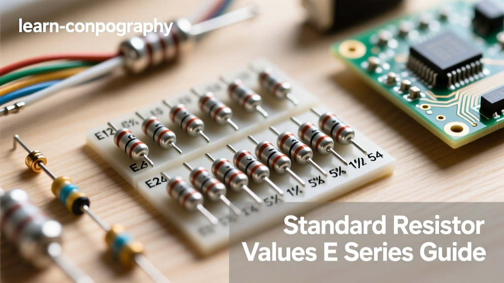

Every electrical engineer and hardware hobbyist has stared at a tangled drawer of through-hole and surface-mount components, trying to decipher faded color bands or cryptic three-digit codes. The global electronics industry does not manufacture every conceivable integer value of resistance. Instead, component manufacturers adhere to the IEC 60063 standard, which dictates specific logarithmic steps for resistance values. Understanding standard resistor values 1 decade at a time reveals the logarithmic genius of this system, ensuring that regardless of the tolerance, there is always a standard value available within the acceptable margin of error.
The Mathematical Foundation of the E-Series
The E-series system is built on a geometric progression. If manufacturers produced resistors in linear increments (e.g., 100Ω, 200Ω, 300Ω), the gap between higher values would be massive, leaving huge blind spots in circuit design. Instead, the IEC 60063 standard divides the base-10 logarithmic decade into equal steps based on the desired tolerance.
The formula for calculating the base values is:
R = 10(n/N)
Where n is the step index and N is the total number of steps in the decade (e.g., 12 for the E12 series). For the E12 series (10% tolerance), the step multiplier is 10(1/12), which equals approximately 1.21. This yields the familiar base sequence: 1.0, 1.2, 1.5, 1.8, 2.2, 2.7, 3.3, 3.9, 4.7, 5.6, 6.8, and 8.2. These base numbers are then multiplied by powers of 10 (from 0.1Ω up to megaohms) to create the full spectrum of available components.
Navigating the Tolerance Spectrum: E6 to E96
While legacy designs and simple pull-up/pull-down networks often rely on 5% (E24) or 10% (E12) components, modern precision analog front-ends demand tighter margins. The E96 series, designed for 1% tolerance, provides 96 distinct values per decade, drastically reducing the need to place multiple resistors in series or parallel to achieve a target impedance.
Why 1% Tolerance is the New Prototyping Baseline
In the past, 1% metal-film resistors were reserved for expensive, calibrated instrumentation. Today, advancements in manufacturing have made 1% thick-film and thin-film SMD resistors virtually as cheap as their 5% counterparts. When designing feedback loops for operational amplifiers, setting the gain of an inverting amplifier requires matched ratios. If you use two 5% resistors, the worst-case gain error can compound to nearly 10%. By standardizing your lab inventory to the E96 series, you eliminate this compounding error.
Expert Insight: Never substitute a 5% carbon-composition or thick-film resistor in a high-impedance ADC voltage divider. The leakage current and voltage coefficient of resistance (VCR) in lower-tier components will introduce non-linear distortion that no amount of software calibration can fully correct.
Component Identification: SMD and EIA-96 Codes
Identifying through-hole resistors relies on the standard 4-band or 5-band color code system. However, as prototyping shifts heavily toward surface-mount devices (SMD) like 0603 and 0402 packages, physical space eliminates the possibility of color bands. Instead, manufacturers use printed alphanumeric codes.
The 3-Digit and 4-Digit Systems
For standard 5% SMD resistors, a 3-digit code is used. The first two digits represent the significant figures, and the third is the multiplier. For example, 103 translates to 10 × 103 = 10,000Ω (10kΩ). For 1% tolerance SMDs, a 4-digit code is often used: 1002 means 100 × 102 = 10,000Ω.
Decoding the EIA-96 SMD Markings
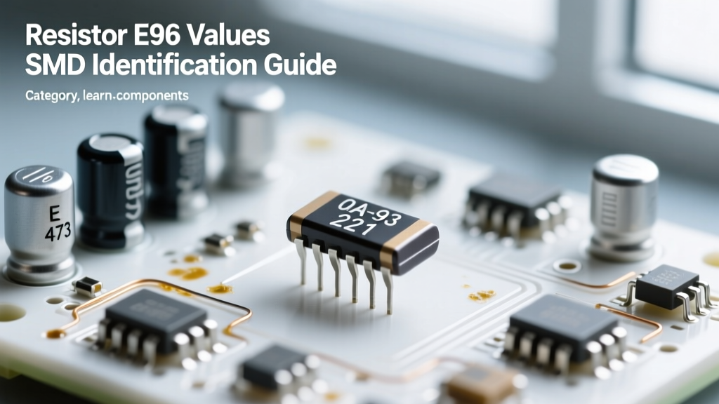
Because 0603 and 0402 packages are too small for 4-digit printing, the industry adopted the EIA-96 marking system for 1% resistors. This system uses two digits followed by a single letter. The two digits correspond to a specific 3-significant-figure value in a lookup table, while the letter denotes the multiplier.
- Code '01' = 100
- Code '68' = 499
- Multiplier 'A' = 100 (×1)
- Multiplier 'C' = 102 (×100)
- Multiplier 'E' = 104 (×10,000)
Therefore, an SMD resistor marked 01C is 100 × 100 = 10,000Ω (10kΩ, 1%). A resistor marked 68E is 499 × 10,000 = 4.99MΩ. Keeping an EIA-96 lookup chart on your workbench is mandatory for modern PCB rework and debugging.
Real-World Failure Modes: TCR and Thermal Drift
Identifying the correct standard value is only half the battle; understanding how that value behaves under thermal stress is what separates a functional prototype from a production-ready design. Every resistor possesses a Temperature Coefficient of Resistance (TCR), measured in parts per million per degree Celsius (ppm/°C).
The Shunt Resistor Trap
A common prototyping mistake is using a standard 1% 0805 thick-film resistor as a current-sense shunt. A typical thick-film resistor has a TCR of ±200 ppm/°C. If your circuit draws enough current to heat the resistor by 50°C above ambient, a 0.1Ω shunt will drift by 1,000 ppm (0.1%). While this sounds small, in a 12-bit or 16-bit analog-to-digital conversion system, this thermal drift will manifest as significant non-linearity and ghosting in your readings. For current sensing, you must bypass standard values and source specialized metal-alloy shunt resistors with a TCR of ±50 ppm/°C or lower.
Quick Reference: Base Decade Multipliers
The table below outlines the base values you will encounter across the most common E-series. Memorizing the E12 and E24 sequences will drastically speed up your component selection during the schematic capture phase.
| E-Series | Tolerance | Values / Decade | Base Sequence (1.0 to 9.1) |
|---|---|---|---|
| E6 | ±20% | 6 | 1.0, 1.5, 2.2, 3.3, 4.7, 6.8 |
| E12 | ±10% | 12 | 1.0, 1.2, 1.5, 1.8, 2.2, 2.7, 3.3, 3.9, 4.7, 5.6, 6.8, 8.2 |
| E24 | ±5% | 24 | Adds: 1.1, 1.3, 1.6, 2.0, 2.4, 3.0, 3.6, 4.3, 5.1, 6.2, 7.5, 9.1 |
| E96 | ±1% | 96 | Includes precise steps like 1.02, 1.05, 1.07, 1.10, 1.13... up to 9.76 |
Best Practices for Lab Inventory Management
To maintain an efficient prototyping environment, adopt a strict binning strategy. Store your 5% (E24) through-hole kits separately from your 1% (E96) metal-film kits. When working on high-speed digital buses (like I2C or SPI pull-ups), standard 5% values are perfectly adequate, as the exact impedance is rarely critical compared to the parasitic capacitance of the trace. However, for any node connected to an op-amp, a voltage reference, or an ADC, default exclusively to the E96 1% series. By deeply understanding the math, identification codes, and thermal realities of the IEC 60063 standard, you ensure your hardware designs are robust, repeatable, and ready for mass production.