
Demystifying the Potentiometer: The Core of Analog Control
When you turn the volume knob on a vintage amplifier, adjust the dimmer on a workbench LED array, or tune the frequency of an analog oscillator, you are interacting with one of the most fundamental components in electronics: the potentiometer. Often colloquially referred to as a 'pot,' this electromechanical device bridges the gap between physical human input and electrical circuit behavior. But what are potentiometers at a fundamental physics level? They are three-terminal resistors with a sliding or rotating contact that forms an adjustable voltage divider. Understanding their internal mechanics, material science, and mathematical behavior is critical for any hardware engineer, DIY enthusiast, or audio technician looking to design robust analog interfaces.
Inside the Housing: Resistive Tracks and Wiper Mechanics
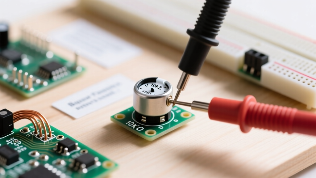
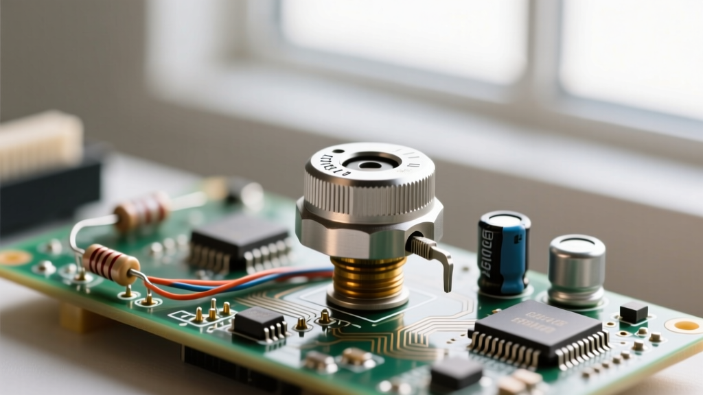
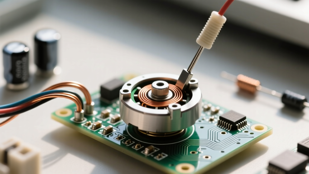
To truly grasp how a potentiometer functions, we must look past the plastic shaft and metal casing. The core of a rotary potentiometer consists of a circular resistive track and a conductive wiper. The track is connected to the two outer terminals (Terminal 1 and Terminal 3), while the wiper is physically attached to the shaft and connected to the center terminal (Terminal 2). As you rotate the shaft, the wiper sweeps across the resistive track, altering the resistance between the wiper and either end of the track.
The Material Science of Resistive Tracks
Not all pots are created equal. The material used for the resistive element dictates the component's resolution, noise floor, power handling, and lifespan:
- Carbon Composition: The most common and cost-effective type. Made from a mixture of carbon dust and a ceramic binder. They offer good resolution but are prone to wear and generate 'scratchy' thermal noise over time.
- Cermet (Ceramic-Metal): Used primarily in high-precision trimpots (like the ubiquitous Bourns 3386 series). Cermet tracks offer excellent temperature stability and low noise, making them ideal for calibration circuits rather than continuous user adjustment.
- Conductive Plastic: The gold standard for professional audio faders and high-end rotary pots. They provide virtually infinite resolution, incredibly low contact noise, and a lifespan exceeding 1,000,000 cycles.
- Wirewound: Constructed by winding nichrome wire around a core. They handle high power (often 5W to 25W) but suffer from low resolution (the wiper jumps from wire to wire) and introduce unwanted inductance in high-frequency AC circuits.
The Three-Terminal Voltage Divider Configuration
The most common way to answer 'what are potentiometers used for' is as a voltage divider. When you wire a DC voltage source (V_in) across Terminal 1 and Terminal 3, the potentiometer acts as two series resistors (R1 and R2) whose values change inversely as the wiper moves. The center terminal (the wiper) outputs a variable voltage (V_out) based on its physical position.
The governing equation, derived from Ohm's Law and detailed in resources like SparkFun's Voltage Divider Tutorial, is:
V_out = V_in × (R2 / (R1 + R2))
Where R1 is the resistance between Terminal 1 and the Wiper, and R2 is the resistance between the Wiper and Terminal 3.
If you apply 5V across a 10kΩ potentiometer and turn the shaft to the exact mechanical center, R1 becomes 5kΩ and R2 becomes 5kΩ. The output voltage at the wiper will be exactly 2.5V. This configuration is the backbone of analog-to-digital converter (ADC) inputs on microcontrollers like the Arduino or ESP32, translating physical rotation into a readable 0-1023 digital value.
Rheostat Mode: Two-Terminal Variable Resistance
While voltage division is common, you can also use a potentiometer as a variable resistor, historically known as a rheostat. This is achieved by using only two terminals: connecting your circuit to Terminal 1 and the Wiper (Terminal 2), while leaving Terminal 3 floating (or safely tying it to the Wiper to prevent open-circuit noise if the wiper momentarily loses contact).
In this configuration, rotating the shaft directly increases or decreases the total resistance in the circuit loop. This is heavily used in current-limiting applications, such as tuning the bias current on a transistor, adjusting the gain of an operational amplifier feedback loop, or manually dimming a low-power incandescent bulb. However, you must be acutely aware of the potentiometer's power rating. Standard PCB-mount pots are typically rated for only 0.1W to 0.5W; pushing high current through them will rapidly burn the carbon track and destroy the component.
Decoding Tapers: Linear vs. Logarithmic Curves
A critical mistake beginners make when sourcing components is ignoring the 'taper'—the mathematical relationship between the physical shaft angle and the electrical resistance ratio. Human perception of sound and light is not linear; it is logarithmic. Therefore, manufacturers engineer the resistive track's geometry to compensate for human senses.
| Taper Code | Name | Resistance Curve Behavior | Primary Application |
|---|---|---|---|
| B-Taper | Linear | Resistance changes at a constant rate relative to shaft rotation (e.g., 50% rotation = 50% resistance). | Microcontroller inputs, motor speed controls, voltage dividers, oscilloscope timebase tuning. |
| A-Taper | Audio (Logarithmic) | Resistance changes slowly at first, then rapidly. Compensates for the human ear's logarithmic perception of volume. | Audio amplifiers, mixer consoles, guitar pedals, synthesizer voltage-controlled amplifiers (VCAs). |
| C-Taper | Reverse Audio | The inverse of the A-Taper. Resistance changes rapidly at first, then slowly. | Specialized cross-faders, specific audio pan-pot configurations, and tone controls. |
If you accidentally use a Linear (B) pot for an audio volume control, the first 20% of the knob rotation will contain 80% of the perceived volume change, making precise adjustments impossible. Conversely, using an Audio (A) pot for an Arduino joystick input will result in skewed, non-linear sensor data that requires complex software mapping to correct.
Real-World Failure Modes and the 'Scratchy Pot' Fix
Because potentiometers rely on physical friction between a metal wiper and a resistive track, they are inherently prone to mechanical degradation. Understanding these failure modes is vital for troubleshooting and repair:
1. Contact Oxidation and Carbon Dust (The 'Scratchy' Sound)
In audio equipment, a failing potentiometer introduces a harsh crackling or 'scratchy' noise when rotated. This occurs because microscopic carbon dust accumulates on the track, or the wiper's contact fingers oxidize, causing micro-interruptions in the electrical path. The Fix: Do not replace the pot immediately. Open the chassis and apply a precise burst of MG Chemicals DeoxIT D5 (specifically the D5 formula, which cleans and lubricates, unlike the F5 fader-only lube) directly onto the track. Rotate the shaft back and forth 30 times to mechanically scrub the oxidation away. This restores 95% of failing vintage pots.
2. Wiper Bounce in Wirewound Pots
When a wiper transitions from one wire loop to the next on a wirewound potentiometer, it can momentarily lose contact or bounce. In a voltage divider configuration, this causes a momentary spike to V_in or ground, which can catastrophically damage sensitive downstream logic if not filtered with a parallel ceramic capacitor (e.g., 100nF).
3. Track Burnout from Over-Wattage
Passing more current than the rated wattage (e.g., running 1A through a 0.5W 100Ω pot) will literally burn a physical trench into the carbon or cermet track, resulting in a permanent open circuit. Always calculate I²R losses before placing a pot in a high-current path.
Prototyping Selection: Trimpots vs. Panel Mounts
When designing a PCB or building a breadboard prototype, selecting the right physical form factor is just as important as the electrical specs. According to comprehensive guides on Electronics Tutorials, matching the mechanical footprint to the user interface requirement prevents costly redesigns.
- Trimpots (Trimming Potentiometers): Designed to be set once with a jeweler's screwdriver and left alone. The Bourns 3296W is an industry-standard, multi-turn (25 revolutions) trimpot perfect for calibrating sensor thresholds or setting DC bias points on a breadboard.
- Panel Mount Pots: Designed for frequent human interaction. The Alpha 16mm series (often found in guitar pedal kits) features a robust metal bushing, a 1/4-inch knurled shaft for standard knobs, and a solder-lug or PCB-mount termination. They are rated for tens of thousands of rotational cycles.
- Slide Potentiometers: Instead of a rotary shaft, these use a linear track. Common in graphic equalizers and lighting DMX consoles, they provide highly visual, spatial feedback of the current parameter state.
Ultimately, mastering what are potentiometers and how to implement them elevates your circuit designs from rigid digital states to fluid, expressive analog interactions. Whether you are tuning a 555 timer astable oscillator or building a high-fidelity tube amplifier preamp, respecting the material limits, taper curves, and power ratings of your potentiometers ensures your hardware performs flawlessly in the real world.