
The Multimeter Illusion: Why You Need an Oscilloscope
Every DIY electronics enthusiast starts with a digital multimeter (DMM). While a DMM is excellent for measuring static DC voltages or calculating RMS averages, it is virtually blind to the dynamic reality of electronic circuits. A multimeter will tell you a microcontroller pin is outputting 2.5V, but it won't tell you if that 2.5V is a clean DC signal, a noisy 5V PWM wave toggling at 50% duty cycle, or a data bus streaming SPI packets. To see the truth of your circuit, you need to learn how to use an oscilloscope.
"In electronics, if you cannot see the signal, you cannot debug the circuit. An oscilloscope translates the invisible domain of time and voltage into a visual map."
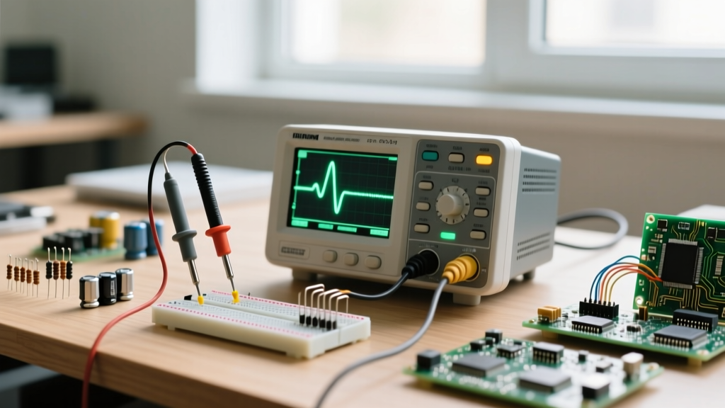
This guide moves beyond basic theory and dives into the practical, real-world application of a Digital Storage Oscilloscope (DSO). We will cover probe compensation, the critical differences in grounding, and execute a step-by-step diagnostic test using an Arduino PWM output.
Anatomy of the DSO: The Graticule and Core Axes
Before connecting probes, you must understand the DSO display grid, known as the graticule. A standard oscilloscope screen is divided into an 8x10 grid (8 vertical divisions, 10 horizontal divisions).
- Vertical Axis (Amplitude): Controlled by the Volts/Div knob. If set to 1V/div, each vertical square represents 1 Volt. An 8-division screen can display an 8V peak-to-peak signal.
- Horizontal Axis (Time): Controlled by the Sec/Div (Timebase) knob. If set to 1ms/div, the entire 10-division screen represents 10 milliseconds of signal history.
Understanding this grid allows you to manually calculate frequency and voltage before the scope's automated measurement tools even kick in, a crucial skill when automated tools fail on noisy signals.
The Probe: Your Critical Link to the Circuit
The most common point of failure for DIYers is misunderstanding oscilloscope probes. A probe is not just a wire; it is a complex impedance-matching network consisting of a resistor and a variable capacitor.
The 1X vs 10X Attenuation Trap
Most passive probes feature a physical switch on the barrel for 1X and 10X attenuation. Always leave your probe in 10X mode for general troubleshooting.
| Probe Setting | Input Impedance | Parasitic Capacitance | Bandwidth | Best Use Case |
|---|---|---|---|---|
| 1X Mode | 1 MΩ | ~100 pF | < 10 MHz | Low-frequency audio, DC power rails |
| 10X Mode | 10 MΩ | ~15 pF | Up to 300 MHz | Digital logic, microcontrollers, PWM |
Using a 1X probe on a high-speed digital circuit introduces massive parasitic capacitance (~100pF) directly into your node, which can distort the signal, cause ringing, or even crash a sensitive microcontroller. Furthermore, you must ensure the Probe Attenuation setting in the scope's software menu matches the physical switch on the probe. If the physical probe is set to 10X but the scope menu is set to 1X, your voltage readings will be exactly 10 times higher than reality.
Probe Compensation: The Square Wave Test
Every time you attach a new probe, you must compensate it. Locate the square wave calibration terminal on the front panel of your scope (usually labeled ~3V, 1kHz). Attach the probe tip and ground clip. If the displayed square wave has rounded corners (under-compensated) or sharp overshoot spikes (over-compensated), use a non-metallic trimmer tool to adjust the tiny screw on the probe's compensation box until the wave is perfectly flat. According to Tektronix's official oscilloscope fundamentals guide, failing to compensate probes is the leading cause of amplitude measurement errors in high-frequency DIY projects.
Step-by-Step DIY Project: Measuring Arduino PWM
Let us apply this knowledge to a real-world scenario. We will measure the Pulse Width Modulation (PWM) signal from an Arduino Uno. Upload the following simple sketch to your Arduino:
void setup() {
  pinMode(9, OUTPUT);
}
void loop() {
  analogWrite(9, 128); // 50% duty cycle
}
On the Arduino Uno, Pin 9 operates at a default PWM frequency of approximately 490 Hz. The period (T) of a 490 Hz signal is roughly 2.04 milliseconds (ms). The voltage will swing between 0V and 5V.
Dialing in the Trigger System
Without a trigger, the oscilloscope will continuously sweep, making the waveform look like a blurry mess. The trigger tells the scope, "Wait until a specific event happens, then draw the screen."
- Trigger Source: Set to CH1 (where your probe is connected).
- Trigger Type: Select Edge.
- Slope: Select Rising (the scope will trigger when the voltage crosses the threshold while moving upwards).
- Trigger Level: Adjust the level knob to 2.5V. Because the signal swings from 0V to 5V, setting the trigger at the exact midpoint ensures a stable lock.
- Sweep Mode: Set to Auto. If the signal drops out, the scope will still draw the baseline. (Use Normal mode when hunting for rare, intermittent glitches).
Setting the Timebase and Voltage Scale
Since one full cycle takes ~2.04 ms, setting the Timebase to 500 µs/div (0.5 ms/div) will display exactly two full cycles across the 10 horizontal divisions. Set the Vertical scale to 1V/div. Your 5V signal will occupy 5 vertical divisions, sitting perfectly in the center of the screen. You can now use the scope's cursors to measure the exact "on" time versus the "off" time to verify the 50% duty cycle.
Hardware Comparison: Best Budget Oscilloscopes for DIYers
If you are building your lab, choosing the right DSO is critical. The market is dominated by a few key players that offer immense value for hobbyists. For deeper community insights and firmware hacks, the EEVblog forum threads on entry-level scopes are an invaluable resource.
| Model | Base Bandwidth | Sample Rate | Channels | Approx. Price (USD) | Best For |
|---|---|---|---|---|---|
| Rigol DS1054Z | 50 MHz (Hackable to 100MHz) | 1 GSa/s | 4 | $399 | General DIY, Arduino/ESP32 debugging |
| Siglent SDS1204X-E | 200 MHz | 1 GSa/s | 4 | $499 | Advanced protocols (I2C/SPI decode included) |
| Hantek DSO5102P | 100 MHz | 1 GSa/s | 2 | $320 | Automotive DIY, basic analog repair |
| Owon HDS272S | 70 MHz | 250 MSa/s | 2 | $150 | Field work, handheld portable diagnostics |
Note: When evaluating sample rate, remember the Nyquist theorem. To accurately reconstruct a 50 MHz signal without aliasing, you need a minimum sample rate of 5x to 10x the bandwidth, making 1 GSa/s the practical minimum for serious digital work.
Critical Safety: The Ground Clip Trap
The most dangerous mistake a DIYer can make with an oscilloscope is misunderstanding the ground clip. The BNC outer shell of every channel on a standard benchtop oscilloscope is tied directly to Earth Ground via the power cord's third prong.
If you are probing a circuit that is not isolated from AC Mains (like a switching power supply or a TRIAC-based dimmer) and you attach the ground clip to a "live" or "hot" node, you will create a dead short circuit directly through your oscilloscope to earth ground. This will instantly destroy the probe, blow the internal traces of the oscilloscope, and potentially cause an explosive electrical arc.
How to avoid this:
- Only use the ground clip on circuits that are galvanically isolated from AC mains (e.g., battery-powered devices, or circuits powered by isolated DC wall warts).
- For mains-referenced circuits, invest in a High-Voltage Differential Probe. This device measures the voltage difference between two points without referencing earth ground.
- Alternatively, use an isolation transformer on the Device Under Test (DUT)—but never float the oscilloscope itself by removing its earth ground prong, as this makes the entire chassis lethal to touch.
Advanced Measurements: Decoding Digital Protocols
Modern DSOs are not just for viewing analog waves; they are protocol analyzers. If you are working with I2C sensors or SPI flash memory, scopes like the Siglent SDS1204X-E feature hardware-accelerated serial decoding. By assigning CH1 to SDA and CH2 to SCL, and setting the trigger to an I2C "Start Condition," the scope will overlay the raw hex data directly onto the waveform. This bridges the gap between hardware debugging and software logic analysis, saving hours of blind troubleshooting.
Conclusion
Learning how to use an oscilloscope transforms you from a parts-swapper into a true electronics diagnostician. By respecting probe capacitance, mastering the trigger system, and strictly observing grounding safety protocols, you can confidently tackle everything from basic Arduino PWM tuning to complex switching power supply repairs. For further reading on signal integrity and advanced probing techniques, refer to SparkFun's comprehensive oscilloscope tutorials to continue expanding your lab skills.