
The RFID Learning Curve: Where to Start
Integrating an RFID module into your electronics repertoire is one of the most rewarding milestones for a maker. Unlike basic sensors that merely read environmental data, RFID (Radio Frequency Identification) allows you to interact with secure, persistent memory and establish wireless authentication systems. However, the jump from blinking an LED to reading and writing encrypted memory blocks requires a structured approach.
This guide is designed as a skill-building path. We will start with the ubiquitous, budget-friendly MFRC522 module, master the SPI protocol and MIFARE memory architecture, and eventually graduate to the advanced PN532 controller for NFC emulation and access control integration.
Stage 0: Understanding the Hardware Landscape
Before soldering a single header pin, you must select the right tool for your current skill level and project requirements. The market is flooded with breakout boards, but they generally fall into three distinct categories based on their underlying silicon and frequency.
| Module / IC | Frequency | Protocols Supported | Avg. Price | Best For |
|---|---|---|---|---|
| MFRC522 (RC522) | 13.56 MHz (HF) | SPI, I2C, UART | $2 - $4 | Beginners, basic tag reading, simple inventory |
| PN532 | 13.56 MHz (HF) | SPI, I2C, HSU (UART) | $8 - $14 | Intermediate makers, card emulation, NFC tags |
| R2000 / UHF Modules | 860-960 MHz (UHF) | UART, USB, Ethernet | $25 - $60+ | Advanced, long-range (up to 10m), warehouse tracking |
Stage 1: Wiring and Protocol Basics (The RC522)
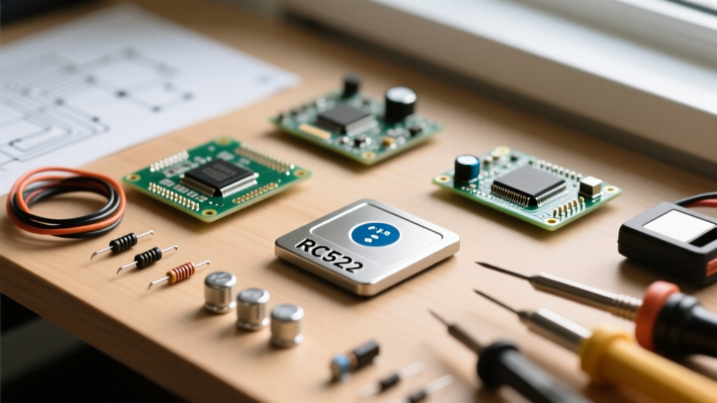
Your journey begins with the MFRC522. This NXP-based IC is the standard entry point for learning RFID. It communicates via SPI (Serial Peripheral Interface), which is an excellent protocol for learning synchronous serial communication.
The 3.3V Logic Trap
The most common failure mode for beginners is frying the RC522 on boot. The MFRC522 IC operates strictly at 3.3V logic. If you are using a 5V microcontroller like the classic Arduino Uno or Mega, connecting the MISO, MOSI, and SCK pins directly will degrade the silicon over time or destroy it instantly. You must use a logic level converter (like a BSS138 or CD4050B chip) or a dedicated 3.3V microcontroller like the ESP32 or Arduino Nano 33 IoT.
SPI Pinout Mapping
When wiring to an ESP32 (which natively uses 3.3V logic), your connections should look like this:
- VCC: 3.3V (Never use 5V)
- GND: Common Ground
- RST: GPIO 21 (Reset pin, active low)
- SDA (SS): GPIO 5 (Slave Select)
- MOSI: GPIO 23 (Master Out Slave In)
- MISO: GPIO 19 (Master In Slave Out)
- SCK: GPIO 18 (Serial Clock)
For a deep dive into the timing diagrams and clock polarity settings required for SPI communication, refer to the Arduino SPI Library Reference. Understanding CPOL and CPHA is crucial when debugging SPI bus conflicts later in your career.
Stage 2: Reading, Writing, and Memory Architecture
Once you can successfully read a tag's UID (Unique Identifier), the next skill to master is interacting with the tag's memory. The most common tags paired with the RC522 are MIFARE Classic 1K cards and fobs.
Deconstructing the MIFARE Classic 1K
A MIFARE Classic 1K tag contains 1024 bytes of EEPROM memory. This memory is not a flat array; it is strictly hierarchical. According to the NXP MIFARE Classic 1K Datasheet, the memory is divided into:
- 16 Sectors (Numbered 0 to 15)
- 4 Blocks per Sector (Numbered 0 to 3)
- 16 Bytes per Block
Critical Warning: Block 3 of every sector is the Sector Trailer. It contains Key A (6 bytes), Access Bits (4 bytes), and Key B (6 bytes). If you write incorrect data to the Access Bits, you can permanently brick that sector, locking yourself out forever. Always calculate access bits using a verified MIFARE access condition calculator before executing a write command.
Authentication and The Default Key
Before reading or writing to Blocks 0, 1, or 2 of any sector, your RFID module must authenticate using either Key A or Key B. Out of the factory, almost all MIFARE Classic tags are secured with the default transport key: FF FF FF FF FF FF. Your C++ or Python code must pass this key array to the PCD_Authenticate() function before attempting memory operations.
Stage 3: Upgrading to the PN532 for Advanced Emulation
As your skills progress, you will hit the hardware limitations of the RC522. The RC522 can only act as a reader/writer (PCD - Proximity Coupling Device). It cannot emulate a card. If your project requires your microcontroller to pretend to be an NFC tag so a smartphone can read it, you must upgrade to the PN532.
Hardware Multiplexing via DIP Switches
The PN532 is a highly versatile NFC controller. On popular breakout boards (like the Elechouse PN532 v3), you will find a set of physical DIP switches labeled I2C, SPI, and HSU. These switches physically route the internal logic to different pins on the breakout header. Learning to read the PN532 schematic and configure these switches is a vital skill for integrating NFC into complex I2C bus systems without causing address collisions.
Host Card Emulation (HCE)
With the PN532, you can configure the module in Target Mode. This allows your ESP32 or Raspberry Pi to dynamically generate an NDEF (NFC Data Exchange Format) message. For example, you can program your microcontroller to emulate an NFC tag containing a Wi-Fi password or a dynamic URL that changes based on sensor inputs. The Adafruit PN532 Guide provides excellent foundational code for initializing the board in NDEF emulation mode.
Stage 4: Real-World Troubleshooting and RF Physics
Working with RFID modules means stepping into the world of RF (Radio Frequency) physics. Code is only half the battle; the physical environment will often sabotage your read ranges.
Antenna Detuning and the Metal Problem
The PCB trace antenna on an RC522 or PN532 is tuned to resonate exactly at 13.56 MHz. If you mount the module directly against a metal enclosure or a carbon-fiber chassis, the parasitic capacitance shifts the resonant frequency. Your read range will drop from 5 centimeters to zero. The Fix: Use ferrite tape shielding behind the antenna, or mount the module on nylon standoffs at least 15mm away from any conductive surfaces.
Signal Integrity on Long SPI Runs
SPI is designed for short-distance, on-PCB communication. If you attempt to run SPI wires longer than 15cm from your microcontroller to your RFID module, you will experience clock skew and data corruption. If your physical design requires the antenna to be far from the MCU, switch to the I2C or UART (HSU) protocol, or use an RS485 transceiver to bridge the gap reliably.
Recommended Tooling for Your Workbench
To accelerate your skill-building path, equip your workbench with the following tools specifically tailored for RFID development:
- Logic Analyzer: A $15 24MHz 8-channel USB logic analyzer is mandatory for debugging SPI/I2C handshake failures between the MCU and the RFID IC.
- MIFARE Toolkit App: Use an Android smartphone with an NXP NFC tag reader app to verify what your microcontroller is actually writing to the tag's memory blocks.
- Assorted Tag Types: Don't just test with MIFARE Classic. Purchase a sample pack containing MIFARE Ultralight, NTAG215, and ICODE SLIX tags to understand how different memory architectures respond to your module's polling commands.
Conclusion
Mastering the RFID module is not just about copying and pasting library code. It requires a deep understanding of logic levels, memory hierarchies, and RF environmental factors. By following this skill-building path—from safely wiring the 3.3V RC522, to navigating MIFARE sector trailers, and finally unlocking the emulation power of the PN532—you transition from a hobbyist assembling kits to an engineer designing robust, secure wireless identification systems.