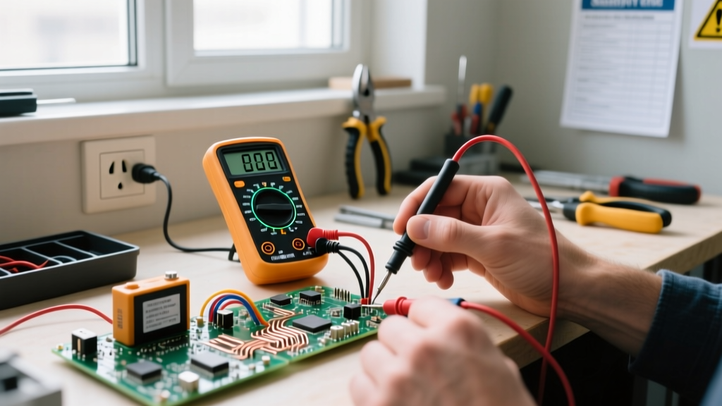

Whether you are wiring a new smart thermostat, troubleshooting a flickering LED strip, or verifying that a wall outlet is dead before replacing a receptacle, understanding how to check voltage with a multimeter is the most critical skill in your DIY arsenal. Voltage is the electrical 'pressure' pushing current through a circuit. Misreading it—or worse, using the wrong multimeter setting—can result in fried microcontrollers, tripped breakers, or severe arc flash injuries.
The Anatomy of a Voltage Reading: AC vs. DC
Before touching any probes, you must identify the type of voltage you are measuring. Multimeters separate voltage into two distinct modes, usually marked on the rotary dial:
- AC Voltage (V~ or VAC): Alternating Current. Used for mains power, wall outlets, and HVAC systems. In North America, this is typically 120V or 240V at 60Hz.
- DC Voltage (V⎓ or VDC): Direct Current. Used for batteries, USB power, solar panels, and microcontroller logic levels (e.g., Arduino 5V or ESP32 3.3V rails).
Essential Gear: Choosing the Right Multimeter for DIY
Not all meters are created equal. For household DIY and low-voltage electronics, you need a meter with the correct Category (CAT) rating. According to Fluke's Multimeter Safety Ratings Guide, CAT III is required for fixed wiring and distribution panels, while CAT IV covers the service entrance and outdoor utility lines.
For most DIYers, the Fluke 117 (approx. $200) is the gold standard because it features non-contact voltage detection (VoltAlert) and LoZ (Low Impedance) mode to eliminate ghost voltages. If you are on a strict budget, the Klein Tools MM400 (approx. $50) is a capable CAT III 600V True RMS meter, though it lacks the advanced safety shielding and fast-blow internal protection of professional models.
Step-by-Step: How to Check Voltage With a Multimeter on AC Outlets
Testing a standard 120V North American NEMA 5-15 receptacle is the most common diagnostic task. Follow this exact sequence to ensure accuracy and safety.
1. Configure the Probes and Dial
Insert the black probe into the COM (Common) jack. Insert the red probe into the VΩ (Volts/Ohms) jack. Never leave the red probe in the Amps (A) or milliamps (mA) jack when testing voltage; doing so will create a dead short across the mains and cause an explosive arc flash.
Turn the dial to V~ (AC Voltage). If your meter is not auto-ranging, select a range higher than your expected voltage (e.g., the 200V or 600V setting, never the 20V setting).
2. The Three-Point Receptacle Test
To verify proper wiring and grounding, you must take three distinct measurements:
- Hot to Neutral: Insert the red probe into the smaller (hot) slot and the black probe into the larger (neutral) slot. Expected reading: 114V to 126V.
- Hot to Ground: Move the black probe to the U-shaped ground hole. Expected reading: 114V to 126V. If this reads zero but Hot-to-Neutral reads 120V, your outlet has an open ground—a severe shock hazard.
- Neutral to Ground: Red probe to neutral, black to ground. Expected reading: 0V to 2V. A reading higher than 5V indicates a loose neutral connection somewhere upstream in your panel, which can destroy sensitive electronics.
3. The 'One-Hand Rule' for High Voltage Safety
When probing live 240V circuits (like a dryer outlet or HVAC disconnect), always use the 'One-Hand Rule'. Keep your non-dominant hand in your pocket or behind your back. As OSHA Electrical Safety Standards emphasize, preventing current from crossing the chest cavity is paramount. If you accidentally touch a live conductor with your left hand while your right hand holds the grounded probe, the current will pass directly through your heart, causing ventricular fibrillation.
Testing DC Circuits: Batteries, LED Strips, and Microcontrollers
DC voltage testing requires attention to polarity. Switch your dial to V⎓ (DC Voltage).
- 9V Alkaline Batteries: Touch red to the smaller (+) terminal and black to the larger (-) terminal. A fresh battery will read between 9.3V and 9.6V. If it reads below 7.5V under no load, it is effectively dead for high-drain DIY projects.
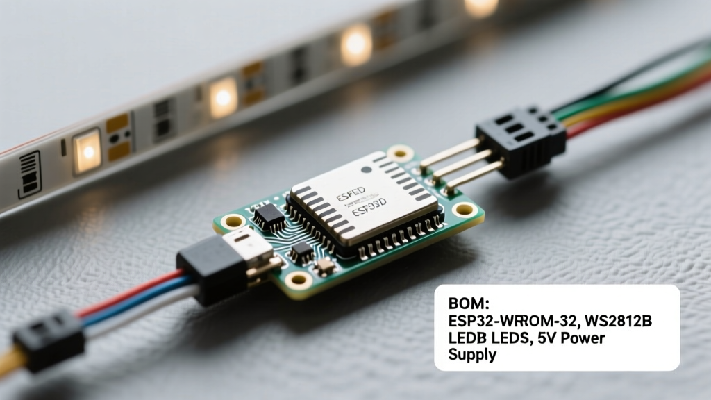
- Addressable LED Strips (WS2812B): Probe the 5V and GND pads on the strip. If your reading drops below 4.7V at the end of a 5-meter strip, you are experiencing voltage drop due to trace resistance. You must inject power at both ends to prevent color shifting.
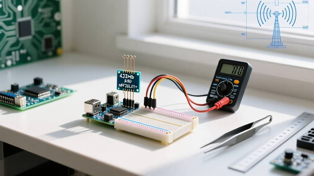
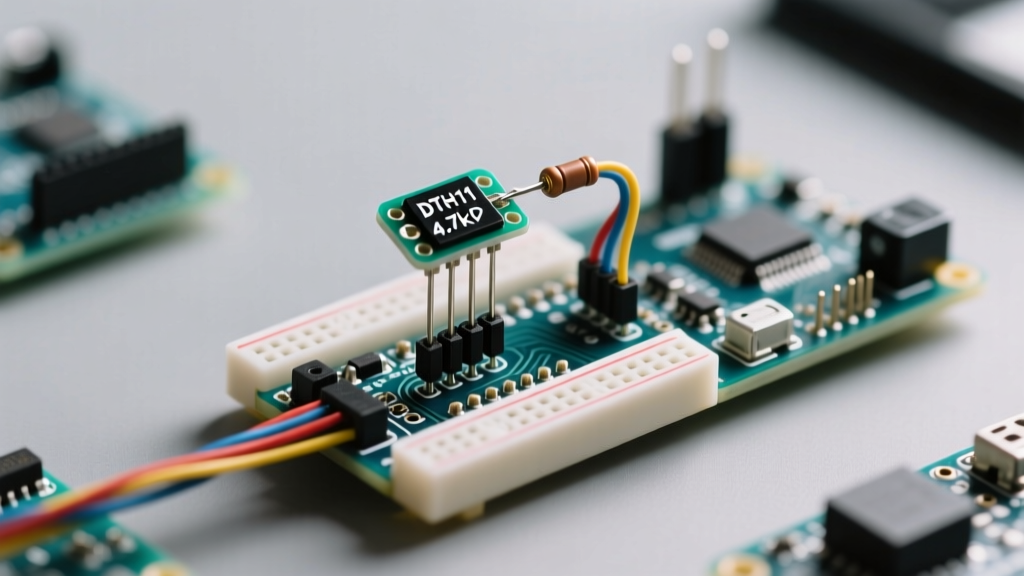
- Arduino / ESP32 Logic Pins: Use fine-tipped probes to measure the 3.3V or 5V VCC rails relative to the GND pin. Fluctuating readings here often indicate a failing onboard voltage regulator or an overloaded peripheral drawing too many milliamps.
Troubleshooting Ghost Voltages and Voltage Drops
One of the most confusing phenomena for DIYers is 'ghost voltage.' When testing a disconnected wire running parallel to a live wire in a conduit, capacitive coupling can induce a phantom voltage reading of 40V to 90V on a standard high-impedance digital multimeter.
The Fix: If your meter has a LoZ (Low Impedance) mode, engage it. LoZ drops the meter's internal resistance from 10 Megohms down to roughly 3 Kilohms, bleeding off the phantom capacitive charge and revealing the true state (0V) of the wire. If your meter lacks LoZ, wire a 100kΩ resistor in parallel with your probes to achieve the same effect safely.
Common Voltage Ranges & Multimeter Dial Settings
| Target Component | Expected Voltage | Dial Setting | Probe Jacks |
|---|---|---|---|
| Standard US Wall Outlet | 120V AC | V~ (Auto or 600) | COM & VΩ |
| US Dryer / Range Outlet | 240V AC | V~ (Auto or 600) | COM & VΩ |
| Car Battery (Engine Off) | 12.4V - 12.7V DC | V⎓ (Auto or 20) | COM & VΩ |
| CR2032 Coin Cell | 3.0V - 3.3V DC | V⎓ (Auto or 20) | COM & VΩ |
| USB-C PD Data Line | 5V to 20V DC | V⎓ (Auto or 20) | COM & VΩ |
The 'Live-Dead-Live' Verification Protocol
Before trusting a zero-voltage reading on a circuit you believe is turned off, you must perform the Live-Dead-Live test. First, test your multimeter on a known live source (like a working outlet) to verify the meter and probes are functioning. Second, test the target circuit to confirm it reads 0V. Finally, test the known live source again. This three-step process ensures your meter didn't blow an internal fuse or suffer a broken probe wire between the first and second tests, which could lead you to touch a live wire thinking it was safe.
Fatal Mistakes to Avoid When Probing Live Mains
The most common way DIYers destroy multimeters—and risk severe injury—is by attempting to measure voltage while the red probe is plugged into the Amps (A) jack. The current jack contains an internal shunt resistor (often less than 0.1 ohms) designed to measure current in series. Plugging this directly across a 120V or 240V AC source creates a massive short circuit. The resulting arc flash can vaporize the probe tips, melt the multimeter casing, and cause third-degree burns.
Expert Rule of Thumb: Always visually verify your probe jack placements before you look at the circuit. Build the muscle memory to check the jacks every single time you pick up the meter.
Furthermore, never attempt to measure the resistance (Ω) or continuity of a live circuit. Multimeters inject a small internal voltage to measure resistance; introducing external mains voltage into this delicate circuitry will instantly fry the meter's internal protection fuses and mainboard ICs.
Final Thoughts on DIY Electrical Diagnostics
Mastering how to check voltage with a multimeter bridges the gap between guessing and knowing. By respecting CAT safety ratings, utilizing the one-hand rule, and understanding the nuances of AC versus DC behavior, you can confidently troubleshoot everything from a flickering smart bulb to a tripped 240V HVAC breaker. Always prioritize safety, verify your meter on a known live source before testing a dead circuit, and keep your probes in top condition to ensure reliable readings for years to come.