
Learning how to operate an oscilloscope is a rite of passage for any electronics enthusiast, electrical engineering student, or DIY hardware hacker. Unlike a multimeter, which gives you a static numerical average, an oscilloscope reveals the dynamic soul of a circuit—showing voltage changes over time, noise, ringing, and digital communication protocols. However, the sheer number of knobs, menus, and BNC connectors can be paralyzing for beginners.
Rather than treating the oscilloscope as a single tool to be memorized, we approach it as a skill-building path. By breaking down the operation into distinct phases—from basic trace stabilization to advanced protocol decoding—you will build muscle memory and diagnostic intuition. This guide is structured to take you from your first power-on to confidently debugging high-speed digital signals.
Phase 1: The Anatomy and Initial Setup (Baseline Skills)
Before twisting knobs, you must understand the canvas. The oscilloscope screen is overlaid with a grid called a graticule. The vertical axis (Y) represents voltage, while the horizontal axis (X) represents time.
Your first practical exercise should always be the "Default Setup." Almost every modern digital storage oscilloscope (DSO), from the entry-level Rigol DS1054Z to the professional Keysight InfiniiVision series, features a dedicated [Default] or [Auto-Scale] button. Pressing this resets the internal sampling, timebase, and trigger systems to a known baseline.
- Step 1: Connect the BNC probe to Channel 1.
- Step 2: Attach the probe tip to the scope’s built-in calibration terminal (usually outputting a 1kHz, 3V square wave).
- Step 3: Connect the ground clip to the calibration ground lug.
- Step 4: Press [Auto-Scale]. You should see a stable square wave. If it looks like a chaotic scribble, proceed to Phase 3.
Phase 2: Mastering Vertical and Horizontal Control
Auto-scale is a crutch; true mastery requires manual control. To operate an oscilloscope effectively, you must learn to manipulate the signal to fit the graticule optimally.
The Vertical System (Voltage)
The Volts/Div knob dictates how much voltage each vertical square on the grid represents. If you are measuring a 5V Arduino logic pin, setting the scale to 1V/Div means the signal will span 5 vertical squares. Use the Vertical Position knob to move the trace up or down, aligning the 0V ground reference with the center horizontal line.
The Horizontal System (Time)
The Sec/Div (Timebase) knob controls the horizontal sweep speed. For a 1kHz signal (which has a period of 1 millisecond), setting the timebase to 250µs/Div will display exactly four complete cycles across a standard 10-division screen.
| Signal Type | Typical Frequency | Suggested Timebase | Coupling Mode |
|---|---|---|---|
| Mains AC Power | 50Hz / 60Hz | 5ms / Div | DC or AC |
| Audio Signals | 20Hz - 20kHz | 50µs - 10ms / Div | AC |
| I2C / SPI Digital | 100kHz - 10MHz | 1µs - 10µs / Div | DC |
| Switching Regulator Ripple | 500kHz - 2MHz | 1µs / Div | AC (with Bandwidth Limit) |
Input Coupling: The Hidden Superpower
According to Tektronix Oscilloscope Fundamentals, understanding input coupling is critical for isolating specific signal characteristics:
- DC Coupling: Passes both AC and DC components. Use this for digital logic and battery-powered circuits.
- AC Coupling: Inserts a series capacitor to block the DC offset. Pro Tip: If you need to measure 50mV of ripple on a 12V DC power rail, DC coupling will force you to use a large Volts/Div setting, hiding the ripple. Switch to AC coupling to block the 12V, allowing you to zoom in to 10mV/Div and see the ripple clearly.
- GND Coupling: Disconnects the input and grounds the amplifier, allowing you to find the exact 0V baseline on the screen.
Phase 3: The Art of Triggering (The Breakthrough Milestone)
The trigger system is the most misunderstood aspect of learning how to operate an oscilloscope. Without a trigger, the scope captures random slices of time, resulting in a blurry, rolling mess. The trigger tells the scope: "Wait until a specific event happens, then capture the waveform."
Edge Triggering Basics
The standard trigger is the Edge Trigger. You define a Trigger Level (a specific voltage) and a Slope (Rising or Falling). The scope will freeze the display only when the signal crosses that exact voltage in the specified direction.
If your trace is rolling horizontally, your trigger level is set outside the voltage boundaries of your signal. For example, if your signal swings from 0V to 3.3V, and your trigger level is set to 4.0V, the scope will never trigger. Fix: Rotate the Trigger Level knob until the trigger icon aligns within the vertical bounds of your live waveform.
Trigger Modes: Auto vs. Normal
- Auto Mode: The scope will trigger if the condition is met, but if it isn’t, it will force a sweep after a timeout so you don’t stare at a blank screen. Best for initial setup.
- Normal Mode: The scope only updates the screen when the exact trigger condition is met. Essential for capturing rare glitches or single-shot events like a button press.
Phase 4: Probing Techniques and Compensation
Your oscilloscope is only as good as the probe connecting it to the circuit. As highlighted in SparkFun’s comprehensive Oscilloscope Tutorial, probes are not just wires; they are complex RC (Resistor-Capacitor) networks.
The 1X vs 10X Dilemma
Most passive probes feature a switch for 1X and 10X attenuation.
- 1X Mode: No attenuation. High sensitivity, but terrible bandwidth (often limited to 5-10MHz) and high capacitive loading on your circuit. Use only for low-frequency audio or slow power-supply ramp-ups.
- 10X Mode: Attenuates the signal by a factor of 10 inside the probe, but drastically reduces capacitive loading and increases bandwidth to 100MHz+. Always default to 10X for digital signals and microcontrollers.
Critical E-E-A-T Warning: If your physical probe is set to 10X, you must go into the oscilloscope’s Channel Menu and set the Probe Attenuation ratio to 10X. If you forget this step, a 3.3V signal will incorrectly read as 33V on your screen, potentially leading to disastrous diagnostic conclusions.
Probe Compensation
Before measuring, you must compensate your probe to match the oscilloscope’s input capacitance. Connect the probe to the calibration square wave. If the corners of the square wave are rounded (overcompensated) or exhibit sharp spikes (undercompensated), use the non-conductive plastic screwdriver included with your probe to adjust the trimmer capacitor on the probe body until the wave is perfectly flat.
Phase 5: Advanced Diagnostics and Protocol Decoding
Once you master voltage, time, and triggering, you can leverage the digital processing power of modern DSOs.
Serial Protocol Decoding
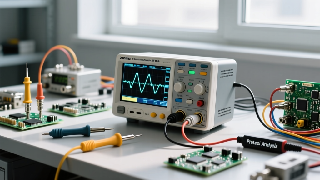
Mid-range scopes like the Siglent SDS1104X-E or Rigol MSO5000 series feature hardware decoders for I2C, SPI, UART, and CAN bus. By assigning Channel 1 to SDA and Channel 2 to SCL, and setting the correct trigger thresholds, the scope will overlay the raw hex data directly over the analog waveform. This allows you to instantly verify if a microcontroller is sending the correct configuration bytes to an I2C sensor.
FFT (Fast Fourier Transform)
When troubleshooting EMI (Electromagnetic Interference) or switching noise, time-domain analysis isn’t enough. Engaging the Math → FFT function converts the time-domain signal into the frequency domain, allowing you to identify the exact frequency of a noise spike (e.g., identifying a 150MHz ringing caused by a poorly routed PCB trace).
Common Beginner Mistakes and How to Fix Them
"The biggest mistake I see junior engineers make is trusting the long ground clip on high-speed signals. The inductance of that alligator clip will create a massive ground loop antenna, showing ringing on the scope that doesn’t actually exist in the circuit." — Senior Hardware Design Engineer
To operate an oscilloscope like a professional, avoid these three common pitfalls:
- Using the Alligator Ground Clip on High Frequencies: For signals above 10MHz (like SPI clocks or switching nodes), remove the plastic sleeve and alligator clip from the probe. Use the ground spring accessory to connect directly to the probe tip. This reduces ground inductance from 50nH to less than 2nH, eliminating phantom ringing.
- Ignoring the Nyquist Theorem: To accurately reconstruct a waveform, your oscilloscope’s sampling rate must be at least 2.5 to 3 times higher than the signal’s highest frequency component. If you are measuring a 50MHz clock, ensure your scope is sampling at a minimum of 500 MSa/s (Mega-samples per second). If you zoom out on the timebase, the scope drops its sampling rate to save memory, which can lead to aliasing and false waveform representations.
- Measuring Mains Voltage with Standard Probes: Standard passive probes are usually rated for CAT I or CAT II up to 300V. Never use them to probe wall outlets or high-power inverters. Use a high-voltage differential probe to avoid short-circuiting the mains through the oscilloscope’s earth ground, which can destroy the scope and pose a lethal shock hazard.
Recommended Oscilloscopes for Your Skill Journey
Your hardware should scale with your skills. Here is a quick framework for choosing your instrument:
- The Hobbyist Baseline (Rigol DS1054Z): A legendary 4-channel, 50MHz scope. Famous in the EEVblog community for a well-documented software hack that unlocks 100MHz bandwidth and advanced triggering options. Perfect for Phase 1 through Phase 3.
- The Prosumer Workhorse (Siglent SDS1104X-E): Features a superior SPO (Super Phosphor Oscilloscope) display engine, lower noise floor, and excellent hardware decoding. Ideal for Phase 4 and Phase 5 diagnostics.
- The Mixed-Signal Upgrade (Keysight InfiniiVision 1000G or 2000X series): If you frequently debug complex digital boards, investing in an MSO (Mixed Signal Oscilloscope) with 16 logic analyzer channels will allow you to trigger on specific digital states while viewing analog ripple simultaneously.
Learning how to operate an oscilloscope is not a weekend project; it is a continuous journey of refining your observation skills. Start with the calibration square wave, master the trigger, respect the probe, and the oscilloscope will become the most powerful diagnostic tool on your workbench.