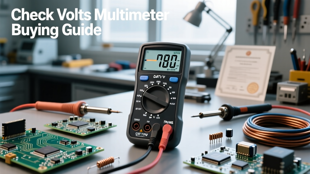

The Core Question: How to Check Volts on Multimeter
If you are searching for exactly how to check volts on multimeter, you are likely standing at the intersection of practical DIY troubleshooting and the need to purchase reliable test equipment. Voltage, fundamentally, is the electrical potential difference between two points. Unlike current, which requires breaking the circuit to measure in series, voltage is always measured in parallel. However, understanding how to measure this potential difference safely and accurately is precisely what should dictate which digital multimeter (DMM) you buy.
Buying a multimeter without understanding the physics and safety parameters of voltage testing is a recipe for blown fuses, inaccurate readings, or catastrophic arc flash incidents. This guide bridges the gap between operational technique and purchasing criteria, ensuring you select a DMM tailored to the specific voltages you intend to test.
Why Your Testing Environment Dictates Your Purchase
Before adding a meter to your cart, you must define the electrical environments you will encounter. The methodology of checking volts changes drastically depending on whether you are probing a 12V DC automotive battery, a 5V DC microcontroller logic line, or a 480V AC three-phase industrial motor.
AC vs. DC Voltage: Matching the Meter to the Mains
Direct Current (DC) flows in one direction, typical of batteries, solar panels, and internal PCB logic. Alternating Current (AC) oscillates, which is what powers your home and industrial grids. When learning how to check volts on multimeter circuits, you must select the correct mode (V⎓ for DC, V~ for AC). From a buying perspective, if you only work on electronics or automotive systems, a basic DC-capable meter suffices. If you touch household wiring or HVAC systems, you absolutely require a meter with robust AC voltage capabilities and appropriate safety ratings.
The True RMS Imperative for Modern Electronics
Cheaper multimeters are 'average-responding'. They assume an AC waveform is a perfect sine wave and multiply the average voltage by a form factor of 1.11 to display the RMS (Root Mean Square) value. However, modern electrical grids are filled with non-linear loads—variable frequency drives (VFDs), LED dimmers, and switched-mode power supplies—that distort the sine wave. If you use an average-responding meter on a distorted wave, your voltage reading could be off by up to 30%. When buying a meter for anything beyond basic residential receptacles, ensure the specifications explicitly state True RMS. True RMS meters use complex internal circuitry to calculate the actual heating effect of the waveform, providing accurate voltage readings regardless of distortion.
Essential Safety Features: Decoding CAT Ratings
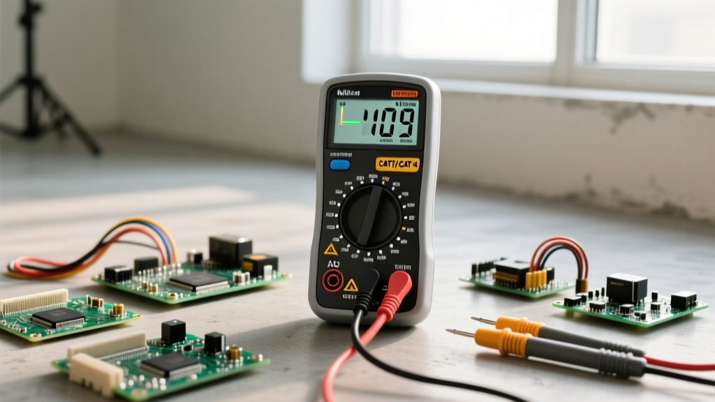
The most critical factor in buying a voltage tester is its Overvoltage Installation Category (CAT) rating, governed by the IEC 61010-1 standard. A meter's CAT rating dictates its ability to survive transient voltage spikes (like a nearby lightning strike or a heavy motor switching off) without exploding in your hands.
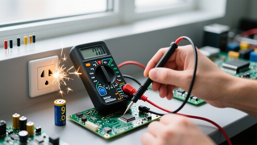
Safety Warning: Never use a CAT II rated meter on a CAT III or CAT IV circuit. The internal clearances and arc-quenching mechanisms are insufficient for higher-energy environments. Always consult OSHA Electrical Safety Standards before working on live panels.
- CAT II: Local level, single-phase receptacles, and appliances. (Up to 1000V).
- CAT III: Three-phase distribution, commercial lighting, and branch circuits. (Up to 1000V).
- CAT IV: Three-phase at utility connections, service entrances, and outdoor overhead lines. (Up to 600V).
When learning how to check volts on multimeter probes in a main breaker panel, a CAT IV 600V or CAT III 1000V rating is non-negotiable. For a deeper dive into transient overvoltage protection, refer to Fluke's comprehensive guide on CAT ratings.
Comparison Chart: Top Multimeters for Voltage Checking
To help you decide which tool to buy based on your voltage testing needs, we have compared three distinct tiers of multimeters popular among electricians and electronics hobbyists.
| Feature | Fluke 117 Electricians True RMS | Klein Tools MM400 | AstroAI DMMS7C |
|---|---|---|---|
| Approximate Price | $210.00 | $45.00 | $15.00 |
| Safety Rating | CAT III 600V | CAT III 600V | CAT II 600V |
| True RMS | Yes | Yes | No (Average) |
| LoZ (Low Impedance) | Yes (VoltAlert) | No | No |
| Best Application | Commercial/Residential Electrical | HVAC & Advanced DIY | Low-Voltage Electronics/Auto |
For professional electricians, the Klein Tools Digital Multimeters lineup and the Fluke 117 represent the gold standard for safely checking mains voltage. The AstroAI is strictly for low-energy DC environments like automotive troubleshooting or Arduino projects.
Step-by-Step: Executing the Voltage Test
Once you have purchased the correct DMM, executing the test requires a disciplined sequence to prevent short circuits and ensure accurate data acquisition.
1. Inspecting the Probes and Ports
Before touching any live circuit, inspect your test leads. The insulation must be free of cracks, and the exposed metal tips should be no longer than 4mm when working in tight panels to prevent accidental bridging between busbars. Insert the black probe into the COM (Common) port and the red probe into the VΩ (Volts/Ohms) port. Never leave the red probe in the Amps (A) port when checking voltage; doing so will create a dead short across the power source, instantly blowing the meter's internal fuse or causing an arc flash.
2. Setting the Dial and Range
Turn the dial to the appropriate voltage setting. If you are using a manual-ranging meter, always start at the highest voltage range (e.g., 600V or 1000V) and step down to increase resolution. If you expect to read 120V AC but set the meter to the 20V range, the display will show an 'OL' (Overload) error. Auto-ranging meters, like the Fluke 117, handle this internally, saving time and reducing dial-setting errors.
3. Making the Parallel Connection
To check volts, place the probes across the component or power source. For a standard US wall receptacle, insert the black probe into the neutral (longer slot) and the red probe into the hot (shorter slot). The meter will display the potential difference. Because voltage testing is done in parallel, the circuit does not need to be dismantled or turned off—in fact, the circuit must be energized to read voltage.
Troubleshooting: The Ghost Voltage Phenomenon
A common point of confusion for beginners learning how to check volts on multimeter circuits is encountering 'ghost voltages'. In commercial wiring, unenergized wires running parallel to energized wires in the same conduit can act as a capacitor, inducing a phantom voltage (often reading between 40V and 90V on a dead wire).
Standard DMMs have a high input impedance (typically 10 Megohms) to prevent loading the circuit. However, this high impedance is sensitive enough to read capacitive coupling. If you are buying a meter for commercial troubleshooting, look for a LoZ (Low Impedance) mode. Engaging LoZ drops the meter's internal resistance to roughly 3 kilohms, effectively bleeding off the phantom capacitive charge and dropping the display to a true 0.0V, confirming the wire is actually dead.
Final Verdict: Aligning Technique with Equipment
Knowing how to check volts on multimeter hardware is only half the battle; possessing the right hardware for your specific electrical environment is the other. If your work is confined to 12V automotive systems or 5V DC breadboards, a budget-friendly, average-responding CAT II meter is perfectly adequate. However, if you are diagnosing 120V/240V residential branch circuits, testing VFDs, or working near main service panels, investing in a True RMS, CAT III or CAT IV rated multimeter with LoZ capabilities is a mandatory safety and accuracy requirement. Buy the meter that matches the highest energy level you will ever probe, and always verify your meter on a known live source before and after every test to ensure the internal fuses and circuitry are intact.