
The Hidden Danger of Incorrect Servo Wiring
When unboxing a new robotics or automation kit, the excitement of assembly often overshadows a critical technical detail: the servo motor pinout. While most hobbyist servos share a superficial resemblance, assuming a universal wiring standard is the fastest way to fry a microcontroller, trip a USB overcurrent protector, or permanently destroy an internal logic IC. Whether you are building a robotic arm with high-torque metal gear servos or a walking biped using smart serial actuators, understanding the specific pin configurations, voltage tolerances, and signal protocols of your kit is non-negotiable.
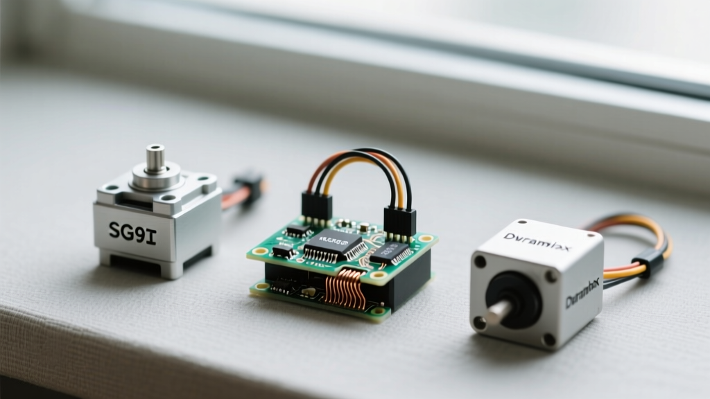
In this equipment roundup and wiring guide, we dissect the pinouts of the most popular servo kits on the market—from the ubiquitous TowerPro SG90 to the advanced ROBOTIS Dynamixel series. We will provide exact wiring schemas, current draw realities, and the necessary interface shields to keep your project alive.
The Anatomy of a Standard PWM Servo Motor Pinout
The vast majority of beginner and intermediate DIY kits utilize standard PWM (Pulse Width Modulation) analog servos. These rely on a 3-wire interface. However, the color coding of these wires is where most mistakes happen, as legacy brands refuse to adopt a unified standard.
Wire Color Variations by Manufacturer
Before plugging a servo into an Arduino or Raspberry Pi GPIO header, you must identify the manufacturer's specific color code. Reversing the VCC (Power) and GND (Ground) pins will instantly short-circuit the internal potentiometer and destroy the motor driver chip.
| Brand / Standard | Ground (GND) | Power (VCC) | Signal (PWM) | Common Kit Models |
|---|---|---|---|---|
| JR / Hitec / TowerPro | Brown | Red | Orange / Yellow | SG90, MG996R, HS-311 |
| Futaba | Black | Red | White | S3003, S3114 |
| Pololu / Generic | Black | Red | White / Yellow | Micro Metal Gearmotors |
For a deep dive into how microcontrollers interpret these PWM signals, the Arduino Servo Library documentation provides an excellent breakdown of the 50Hz pulse timing required to map degree angles to pulse widths.
Heavy-Duty Kits: MG996R and DS3218 Power Requirements
Upgrading to a heavy-duty kit featuring the MG996R (metal gear, ~13kg/cm torque) or the DS3218 (20kg/cm torque) introduces a massive power bottleneck. The physical servo motor pinout remains identical to the standard 3-wire PWM layout, but the electrical reality changes drastically.
The Arduino 5V Pin Trap
A standard Arduino Uno 5V pin can safely supply roughly 400mA to 500mA. An MG996R under stall load can draw 2.5 Amps. If you wire an MG996R directly to your microcontroller's 5V and GND pins, the sudden current draw will cause a severe voltage drop (brownout). The microcontroller will reset unpredictably, and the onboard voltage regulator may overheat and fail.
Expert Rule of Thumb: Never power servos drawing more than 800mA directly from a microcontroller's logic pins. Always use a dedicated BEC (Battery Eliminator Circuit) or a high-current servo shield, ensuring the GND of the external power supply is tied directly to the GND of the microcontroller to establish a common signal reference.
Smart Serial Servos: Breaking Down the Dynamixel Pinout
For advanced robotics kits, standard PWM is insufficient due to cable clutter and lack of positional feedback. Enter smart serial servos, like the ROBOTIS Dynamixel XL430-W250. These actuators feature internal PID controllers, temperature sensors, and daisy-chain capabilities.
TTL Serial vs. RS485 Wiring Harnesses
The Dynamixel pinout abandons the 3-pin JR connector for a 4-pin JST PH 2.0mm connector. However, only three pins are actively used for TTL communication. According to the official ROBOTIS e-Manual for the XL430-W250, the pinout is as follows:
- Pin 1: GND (Ground)
- Pin 2: VDD (Power, typically 12V for X-series)
- Pin 3: DATA (TTL Serial Half-Duplex)
- Pin 4: NC (Not Connected / Reserved)
Because these servos use half-duplex serial communication, you can daisy-chain up to 253 servos on a single UART bus. However, you must use a specialized communication shield (like the U2D2 or an Arduino shield with a 74LS241 buffer) to handle the half-duplex TX/RX switching. Wiring a standard 5V PWM signal to the DATA pin of a 12V Dynamixel will not work and may damage the serial transceiver.
Continuous Rotation vs. Positional Servos
Kits designed for differential drive rovers often include continuous rotation servos (e.g., the FS90R or Parallax Continuous Rotation Servo). The physical servo motor pinout and wire colors are identical to their positional counterparts. The difference lies entirely inside the casing: the internal potentiometer has been disconnected from the output shaft, and the mechanical hard stops have been removed.
When wiring these to a PWM driver, a 1500µs pulse width (90 degrees) commands the motor to stop. A pulse width of 2000µs commands full speed clockwise, and 1000µs commands full speed counter-clockwise. Because there is no positional feedback, you cannot command these servos to move to a specific angle; they act strictly as variable-speed gearmotors.
Kit Roundup: Matching Servos to Microcontroller Shields
To help you select the right interface for your specific kit, we have compiled a compatibility matrix detailing the required hardware based on the servo motor pinout and power requirements.
| Servo Kit Model | Pinout Type | Operating Voltage | Recommended Interface Shield |
|---|---|---|---|
| TowerPro SG90 (Micro) | 3-Wire PWM (JR) | 4.8V - 6.0V | Direct to MCU GPIO (Max 2 servos) |
| MG996R (High Torque) | 3-Wire PWM (JR) | 4.8V - 7.2V | PCA9685 16-Channel PWM Driver + 5V 5A BEC |
| DS3218 (20kg Digital) | 3-Wire PWM (JR) | 5.0V - 8.4V | Adafruit 16-Channel Servo Shield + 6V LiPo |
| Dynamixel XL430-W250 | 4-Pin JST (Serial TTL) | 9.0V - 12.0V | ROBOTIS OpenRB-150 or U2D2 Interface |
| LewanSoul LX-16A | 3-Pin Serial (I2C-like) | 4.8V - 8.4V | LewanSoul Sensor Adapter (Arduino I2C) |
For comprehensive current draw calculations and wiring safety margins across various RC and robotic actuators, the Pololu RC Servo Guide remains an indispensable reference for kit builders.
Troubleshooting Common Pinout and Wiring Failures
Even with the correct pinout memorized, physical wiring errors in DIY kits are common. Here is how to diagnose the three most frequent servo-related failures:
1. The "Jittering" Servo
Symptom: The servo twitches erratically or hums without holding a solid position.
Cause: Signal noise or inadequate grounding. If you are using long, unshielded extension cables for your PWM wires, electromagnetic interference (EMI) from nearby DC motors can corrupt the 50Hz pulse.
Fix: Twist the PWM signal wire around the GND wire to create a makeshift twisted-pair cable, or add a 100µF electrolytic capacitor across the VCC and GND pins at the servo end.
2. The Brownout Reset Loop
Symptom: Your microcontroller resets every time the servo attempts to move under load.
Cause: The servo is drawing peak stall current from the microcontroller's onboard voltage regulator, dropping the logic voltage below the MCU's minimum threshold.
Fix: Separate the logic power from the motor power. Wire the servo VCC directly to a high-discharge LiPo battery or BEC, and ensure a thick gauge wire connects the Battery GND to the MCU GND.
3. The "Dead on Arrival" Serial Servo
Symptom: A smart serial servo (like the LX-16A or Dynamixel) does not respond to software commands, and the LED indicator remains off.
Cause: Reversing the VCC and GND pins on a serial harness. Unlike simple PWM servos which might just fail to move if wired backward, smart servos contain sensitive microcontrollers and serial transceivers that are instantly destroyed by reverse polarity.
Fix: Prevention is the only cure. Always use a multimeter to verify the VCC and GND pins on custom-made JST harnesses before plugging in a serial servo. Most modern smart servos lack reverse-polarity protection diodes to save internal space and reduce cost.