
The Verdict: A Flawed but Unbeatable Budget Tool
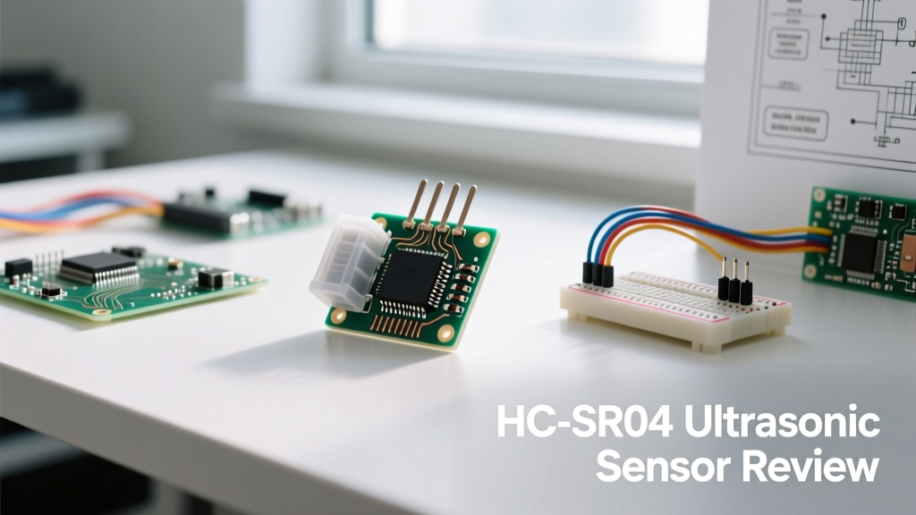
The HC-SR04 ultrasonic sensor module is arguably the most recognized distance-measuring component in the hobbyist electronics ecosystem. Priced at a mere $1 to $3, it has been the default choice for Arduino-based robotics, DIY parking sensors, and fluid level monitors for over a decade. But as microcontrollers have evolved toward 3.3V logic and environmental robustness, does this legacy 40kHz transducer still deserve a spot on your workbench? In this comprehensive tool review, we tear down the HC-SR04, expose its notorious real-world failure modes, and benchmark it against modern alternatives to help you decide when to use it—and when to throw it in the scrap bin.
If you are building an indoor, 5V-tolerant prototype where a 5mm margin of error is acceptable, the HC-SR04 remains an unbeatable value proposition. However, for precision robotics, outdoor applications, or native 3.3V microcontrollers like the Raspberry Pi Pico or ESP32, the HC-SR04 is a liability. It requires external level-shifting resistors, suffers from acoustic crosstalk, and lacks any ingress protection. We rate it a 3.5/5 for beginners, but a 1/5 for industrial or advanced prototyping.
Hardware Anatomy and Core Specifications
To understand the sensor's limitations, you must understand its physical design. The module consists of two silver aluminum mesh transducers: one acts as a transmitter, the other as a receiver. Behind them lies a simple PCB typically populated with an 8-bit microcontroller (often an unmarked SOP-16 chip) and an LM324 quad op-amp for signal conditioning.
| Parameter | Specification | Real-World Reality |
|---|---|---|
| Operating Voltage | 5V DC | Fails erratically on 3.3V pins |
| Operating Current | 15mA (Active) | Spikes during 40kHz burst |
| Ranging Distance | 2cm - 400cm | Reliable only up to ~250cm |
| Accuracy | 3mm | Highly dependent on temperature |
| Measuring Angle | 15° Cone | Wider in practice; catches edge reflections |
| Trigger Input | 10µs TTL Pulse | Requires precise timing in code |
The 5V vs. 3.3V Logic Trap
The most common reason makers abandon the HC-SR04 is the logic level mismatch. The sensor requires a 5V trigger pulse to initiate the 40kHz ultrasonic burst. More importantly, its Echo pin outputs a 5V HIGH signal for the duration of the sound wave's flight time. If you connect this Echo pin directly to a 3.3V GPIO on an ESP32, Raspberry Pi, or nRF52, you risk permanently frying the microcontroller's input buffer.
The Workaround: You must implement a voltage divider. Using a 1kΩ resistor between the Echo pin and the GPIO, and a 2kΩ resistor from the GPIO to ground, will safely drop the 5V signal to ~3.3V. While this costs less than $0.05 in components, it adds wiring complexity and parasitic capacitance, which can occasionally round off the sharp edges of the Echo pulse, leading to microsecond timing errors.
Real-World Failure Modes and Troubleshooting
In controlled laboratory settings, the HC-SR04 performs adequately. In the real world, it is highly susceptible to environmental physics. Here are the primary failure modes we encounter in the ElectricalFlux lab:
1. Temperature Drift
Ultrasonic sensors calculate distance by measuring the time-of-flight (ToF) of a sound wave, assuming the speed of sound is a constant 343 meters per second. However, the speed of sound changes by approximately 0.6 m/s for every 1°C change in temperature. If your sensor is calibrated for a 20°C room but deployed in a 5°C garage, the speed of sound drops to ~334 m/s. Over a 200cm distance, this temperature delta introduces a massive 5.4cm error. Advanced implementations must pair the HC-SR04 with a DS18B20 temperature probe to dynamically adjust the speed of sound variable in the firmware using the formula: distance_cm = (duration_us / 2.0) * (331.3 + 0.606 * temp_c) / 10000.0;
2. The Acoustic Blind Spot and Crosstalk
The HC-SR04 has a hardcoded blind spot of roughly 2cm. The transmitter burst rings the receiver transducer; the op-amp circuit blanks the receiver for a few milliseconds to prevent false triggers. Any object closer than 2cm will cause the sensor to time-out or return a maximum range error. Furthermore, if you deploy multiple HC-SR04 modules on a single robot chassis, acoustic crosstalk will occur. Sensor A will inevitably detect the 40kHz bounce from Sensor B, resulting in phantom obstacles. You must stagger their trigger pulses by at least 50ms in your code loop.
Pro-Tip: Never use the standarddelay()function to stagger sensors. Use non-blockingmillis()timers to fire sensors sequentially, ensuring the acoustic decay of one burst finishes before the next begins.
3. Mechanical Resonance and Mounting
The aluminum mesh transducers are highly sensitive to mechanical coupling. If you mount the HC-SR04 directly to a vibrating robot chassis or a motorized pan/tilt servo using rigid screws, the chassis vibrations will transfer into the receiver transducer. The LM324 op-amp will interpret this low-frequency mechanical noise as acoustic echoes, resulting in a "phantom wall" effect where the sensor reads a constant 10-20cm distance regardless of actual obstacles. Always mount the HC-SR04 using rubber grommets or double-sided foam tape to isolate it from high-frequency chassis vibrations.
HC-SR04 vs. Modern Alternatives
If your project demands reliability, the market offers vastly superior alternatives today. According to acoustic engineering guidelines from MaxBotix, premium ultrasonic sensors utilize superior DSP (Digital Signal Processing) to filter out background noise and temperature variations. Here is how the HC-SR04 stacks up against modern upgrades:
| Module | Logic Level | Environment | Price (Approx) | Best Use Case |
|---|---|---|---|---|
| HC-SR04 | 5V Only | Indoor / Dry | $1.50 | Basic Arduino learning |
| RCWL-1601 | 3.3V / 5V | Indoor / Dry | $2.50 | ESP32 / Pi Pico projects |
| JSN-SR04T | 5V Only | Outdoor / Wet | $6.00 | Car parking / Sump pumps |
| TF-Luna (LiDAR) | 3.3V / 5V | Indoor / Dusty | $18.00 | Precision drones / Robotics |
For ESP32 users, the RCWL-1601 is the direct drop-in replacement. It shares the exact same footprint, pinout, and timing protocol as the HC-SR04 but features native 3.3V compatibility and slightly better noise rejection on the receiver op-amp. For outdoor or fluid-level applications, the JSN-SR04T separates the transducer from the PCB via a 2.5-meter cable, allowing you to keep the electronics dry while the waterproof probe sits in the elements.
Code Optimization: Implementing a Median Filter
The raw output of the HC-SR04 is notoriously jittery. A single stray acoustic reflection can cause the distance reading to spike from 50cm to 400cm for a single frame. Relying on a single digitalRead() is a recipe for robotic collisions.
To fix this, implement a median filter rather than a simple average. An average is easily skewed by a single massive outlier (e.g., a 400cm timeout reading). A median filter takes 5 to 9 rapid samples, sorts them, and selects the middle value. This effectively ignores acoustic anomalies. You can find excellent examples of non-blocking median filtering in the SparkFun Inventor's Kit documentation, which remains a gold standard for sensor debouncing.
Final Recommendation: Should You Buy It?
The HC-SR04 ultrasonic sensor module is a relic of a 5V-dominated era, yet it survives due to sheer economic momentum. As reviewed on Components101, its internal circuitry is basic but functional for low-stakes environments.
Buy the HC-SR04 if: You are teaching a beginner's Arduino class, building a simple indoor trash-can lid opener, or prototyping a concept where budget is the absolute primary constraint.
Skip the HC-SR04 if: You are using 3.3V logic (ESP32/STM32), building an outdoor robot, measuring fluid levels, or require sub-centimeter accuracy. In these cases, spend the extra $4 for a JSN-SR04T or invest in a Time-of-Flight (ToF) optical sensor like the VL53L1X, which operates entirely independently of acoustic physics and temperature drift.