
The Maker's Golden Rule: The ESP8266 WiFi module is a 3.3V logic device that can draw up to 430mA during RF transmission bursts. Never power it directly from an Arduino Uno's 3.3V pin, and always use a dedicated LDO with adequate decoupling capacitance.
Hardware Matrix: Choosing the Right ESP8266 Variant
When makers refer to an ESP8266 WiFi module, they are usually talking about one of four common hardware implementations. Understanding the differences in flash memory, GPIO availability, and USB-to-UART integration is critical for project planning. According to the Espressif ESP8266 Technical Reference Manual, the underlying Tensilica L106 32-bit RISC CPU remains the same across variants, but the supporting circuitry dictates your design constraints.
| Variant | Flash Size | Usable GPIOs | USB-UART Chip | Best Use Case |
|---|---|---|---|---|
| ESP-01S | 1MB | 2 (GPIO0, GPIO2) | None (Requires FTDI) | Simple AT-command relays, space-constrained IoT nodes. |
| ESP-12F | 4MB | 11 | None (Requires FTDI) | Custom PCB designs, battery-operated deep-sleep sensors. |
| NodeMCU V3 (LoLin) | 4MB | 11 | CH340G | Prototyping, breadboarding, educational environments. |
| Wemos D1 Mini | 4MB | 11 | CH340G / CP2104 | Compact projects, stacking shields, permanent installs. |
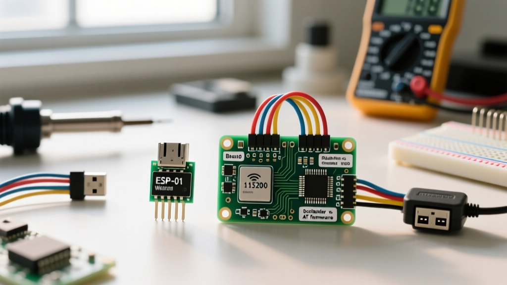
Deep Dive on the ESP-01S: The ESP-01S is notorious for confusing beginners. Unlike the older ESP-01 (which often shipped with 512KB flash), the 'S' variant includes 1MB of flash and a blue LED tied to GPIO2. Because GPIO2 must be pulled HIGH at boot to enter Flash Boot mode, this LED will briefly flicker on startup. Furthermore, GPIO0 and GPIO2 are the only broken-out pins, meaning you cannot use hardware SPI or I2C without severe software bit-banging workarounds.
Power Delivery and the Brownout Detector
The most frequent cause of failure in ESP8266 WiFi module projects is inadequate power delivery. When the module initializes its RF frontend and connects to an access point, current draw spikes to approximately 430mA for a few hundred milliseconds. If your power supply cannot source this current, or if the trace inductance is too high, the internal brownout detector will trigger a hardware reset.
Solving Power Sags
- The LDO Bottleneck: Cheap NodeMCU clones use the AMS1117-3.3 linear regulator. While rated for 800mA, it lacks adequate heatsinking on small PCBs and will thermally throttle or drop out around 500mA. For high-duty-cycle WiFi transmission, use an external switching buck converter (like the MP2307DN) set to 3.3V.
- Decoupling Capacitance: You must place a low-ESR 100µF to 470µF electrolytic or tantalum capacitor directly across the VCC and GND pins of the ESP-12F or ESP-01S. A 100nF ceramic capacitor alone is insufficient to handle the low-frequency RF envelope spikes.
- USB Port Limits: Standard USB 2.0 ports are limited to 500mA. After accounting for the LDO dropout voltage and quiescent current, a NodeMCU powered via USB may brownout if you simultaneously drive high-current peripherals like NeoPixel LED strips.
Boot Mode Pin Strapping Matrix
The ESP8266 does not have a dedicated "boot" button on the silicon level. Instead, it samples the logic states of specific GPIO pins during the first few clock cycles after reset or power-on. This is known as pin strapping. If your external circuitry forces these pins into the wrong state, the module will fail to boot or fail to accept a new sketch.
| Boot Mode | GPIO0 | GPIO15 (MTDO) | GPIO2 | Typical Trigger |
|---|---|---|---|---|
| UART Download (Flashing) | LOW | LOW | HIGH | Pressing "FLASH" button on NodeMCU. |
| Flash Boot (Normal Run) | HIGH | LOW | HIGH | Standard power-on / Reset button. |
| SDIO Boot | HIGH | HIGH | HIGH | Rarely used; SD card boot mode. |
Crucial Design Note: GPIO15 must always be pulled LOW (via a 10kΩ resistor to GND) for normal operation. If you connect a relay or sensor to GPIO15 that pulls it HIGH at startup, the ESP8266 will enter SDIO boot mode and hang. Similarly, GPIO0 must be pulled HIGH via a 10kΩ resistor to VCC. The "FLASH" button on development boards simply grounds GPIO0 when pressed.
Firmware Ecosystem: AT Commands vs. Arduino Core
Historically, the ESP8266 WiFi module was used as a dumb WiFi modem attached to an Arduino Mega via Serial, controlled by the Espressif AT Command Set. Today, this is largely considered an anti-pattern for new designs due to the complexity of parsing asynchronous UART strings and the limited baud rate stability.
Modern makers overwhelmingly use the Arduino Core for ESP8266, which compiles standard C++ directly to the Tensilica architecture. This allows the ESP8266 to act as the primary microcontroller, handling sensor reading, logic, and WiFi stack management simultaneously. For rapid IoT prototyping, MicroPython is also a viable alternative, though it consumes roughly 300KB of RAM just for the interpreter, leaving less room for large TLS certificates and JSON payloads.
Serial Baud Rate Quick Reference
- 74880 Baud: The hardware boot ROM outputs its initialization log at this odd baud rate. If you see garbled text at 115200 upon power-on, switch your serial monitor to 74880 to read the boot strapping messages and exception codes.
- 115200 Baud: The default baud rate for the Arduino Core Serial output and standard AT firmware communication.
- 9600 Baud: Older AT firmware versions defaulted to 9600. You can permanently change the AT firmware baud rate using the command
AT+UART_DEF=115200,8,1,0,0.
Troubleshooting Fatal Exceptions and Watchdog Resets
When the ESP8266 crashes, it dumps a hexadecimal stack trace to the serial console. Understanding these codes is the difference between hours of frustration and a five-minute fix.
The Watchdog Timer (WDT) Reset
The ESP8266 runs a background software watchdog that requires the main loop to yield control back to the RTOS (which manages the WiFi stack) at least every 2-3 seconds. If you write a blocking while() loop waiting for a sensor, or use excessive delay() calls without yielding, the RTOS starves, the WiFi stack collapses, and the hardware WDT resets the chip.
The Fix: Replace blocking loops with non-blocking state machines. If you must wait, use yield(); or delay(1); inside your loop to feed the watchdog.
Common Exception Codes Lookup
- Exception (9): LoadStoreAlignment Cause. You attempted to read or write a 32-bit integer from a memory address that is not divisible by 4. This frequently happens when casting byte arrays directly to
uint32_tpointers without usingmemcpy(). - Exception (28): LoadProhibited Cause. The CPU tried to read from an invalid memory address (often a null pointer). Check your arrays, ensure your objects are properly instantiated, and verify that you aren't trying to read from a disconnected I2C sensor pointer.
- Exception (29): StoreProhibited Cause. Similar to Exception 28, but triggered when attempting to write to an invalid memory address. Common in String manipulation where buffer overflows corrupt the heap.
Final Maker Checklist for Deployment
Before soldering your ESP8266 WiFi module into a permanent enclosure, verify the following: disable WiFi.setSleepMode(WIFI_NONE_SLEEP) if you are running on battery (it forces the RF radio to stay active, drawing 80mA continuously), ensure your I2C pull-up resistors are tied to 3.3V and not 5V, and confirm that your power supply can handle the 430mA TX spike without dropping below 3.1V. Mastering these hardware quirks transforms the ESP8266 from a frustrating toy into an incredibly reliable IoT workhorse.