
Transitioning from Dev Board to Bare Silicon
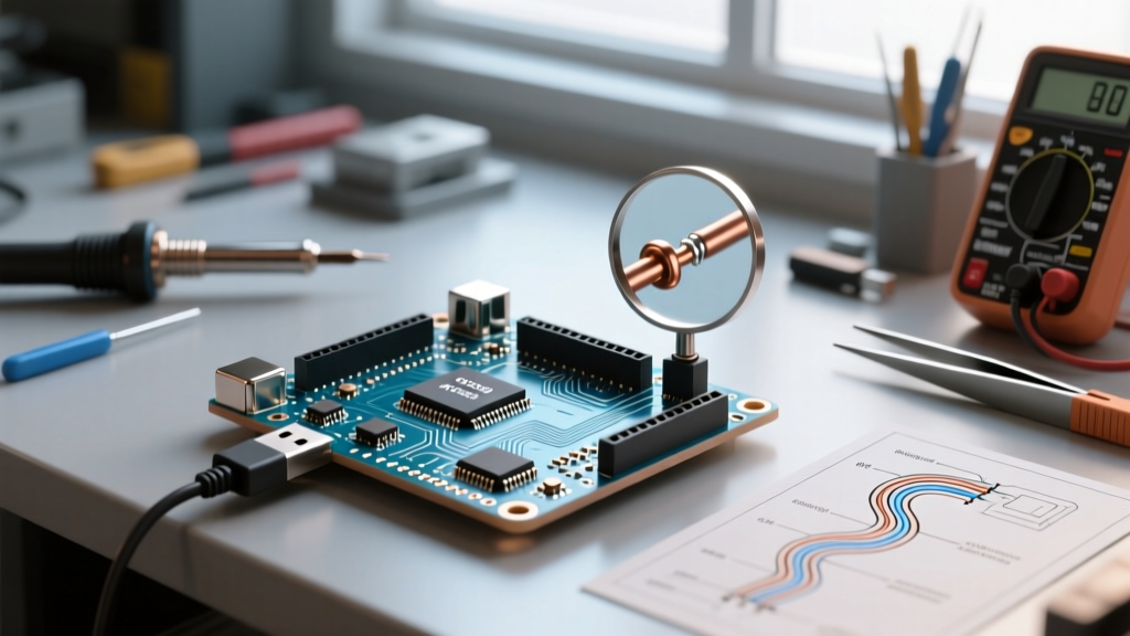
Prototyping on an Arduino Uno or Nano is an excellent way to validate firmware logic, but transitioning to a production-ready custom printed circuit board (PCB) requires a fundamental shift in hardware design. When you deploy the Arduino as microcontroller rather than relying on the development board ecosystem, you strip away the USB-to-serial bridges, linear voltage regulators, and debugging LEDs. This yields a lean, power-efficient, and cost-effective product. This migration guide details how to extract the ATmega328P for standalone operation, navigate oscillator edge cases, configure auto-reset circuits, and evaluate modern 32-bit upgrades within the Arduino IDE ecosystem for 2026 production runs.
Phase 1: Designing the ATmega328P Standalone Circuit
The ATmega328P remains a staple for low-power, low-complexity sensor nodes. Migrating from the DIP-28 package on a breadboard to the TQFP-32 surface-mount package for production requires strict adherence to decoupling and clocking rules. According to the official Microchip ATmega328P datasheet, the chip requires specific external components to operate reliably outside the Arduino bootloader environment.
Critical Passive Components
- Decoupling Capacitors: You must place a 100nF (0.1µF) X7R ceramic capacitor as physically close as possible to every VCC and GND pin pair. The TQFP-32 package has multiple VCC pins; neglecting even one will result in erratic ADC readings and random brown-out resets.
- Bulk Capacitance: A 10µF to 47µF tantalum or low-ESR electrolytic capacitor at the main power entry point handles transient current spikes when the MCU switches multiple I/O pins simultaneously.
- Reset Pin Pull-Up: The PC6 (RESET) pin is active low and highly susceptible to EMI. A 10kΩ resistor tied to VCC is mandatory. For harsh industrial environments, add a 100nF capacitor from RESET to GND to filter high-frequency noise, but be aware this will slow down the programming handshake.
Phase 2: Clocking and Power Edge Cases
One of the most common failure modes when migrating to a standalone ATmega328P is improper clock configuration and Brown-out Detection (BOD) settings.
External Crystal vs. Internal RC Oscillator
The standard Arduino bootloader expects a 16MHz external crystal (HC49/S or SMD 3215 package) with two 22pF load capacitors. This provides the timing accuracy required for high-baud-rate UART communication (e.g., 115200 baud). However, if your application relies on low-power sleep modes or I2C/SPI sensors that tolerate slight timing drift, you can eliminate the crystal and load caps by burning a custom bootloader configured for the 8MHz internal RC oscillator. This saves approximately $0.45 in BOM costs and reduces the PCB footprint, but it limits reliable UART baud rates to 38400 or lower due to the internal oscillator's ±10% factory tolerance.
Brown-out Detection (BOD) Configuration
The default Arduino fuse settings enable BOD at 2.7V. If your standalone device is powered by a 3.3V coin cell (like a CR2032) that drops to 2.0V under load, the MCU will continuously reset or, worse, corrupt the EEPROM during write cycles. You must use an In-System Programmer (ISP) to change the extended fuse byte to set the BOD threshold to 1.8V or disable it entirely if your firmware implements manual voltage monitoring via the internal bandgap reference.
CRITICAL WARNING: When modifying fuse bits via AVRDUDE or the Arduino IDE ISP programmer, never enable the RSTDISBL (Reset Disable) fuse unless you have a High-Voltage Parallel Programmer (HVPP) on hand. Enabling this fuse repurposes the RESET pin as a standard I/O pin and permanently bricks the chip for standard ISP programming. Refer to the Arduino Standalone Breadboard Guide for safe fuse configurations.
Phase 3: The Auto-Reset & ISP Programming Flow
On a standard Arduino Uno, the DTR (Data Terminal Ready) signal from the USB-to-serial chip automatically resets the microcontroller to trigger the bootloader. On a custom PCB, you must replicate this if you intend to program the board via a USB-to-serial adapter (like an FTDI FT232RL or CH340G) post-assembly.
Implementing the DTR Auto-Reset Circuit
To enable auto-reset without a physical button press during firmware updates, route the DTR line from your serial adapter through a 100nF capacitor directly to the RESET pin. This capacitor acts as a differentiator, converting the DTR voltage drop into a brief negative spike that triggers the reset. Ensure you maintain the 10kΩ pull-up resistor on the RESET line; without it, the capacitive spike will not recover to a logic HIGH state, leaving the MCU in a perpetual reset loop.
For initial bootloader burning, you will need an ISP header. The standard AVR 2x3 ICSP header (MISO, VCC, SCK, MOSI, RESET, GND) should be included on your first-revision PCB to allow programming via a USBasp or a secondary Arduino acting as an ISP programmer.
Phase 4: 2026 Migration Matrix: AVR vs. ARM vs. Xtensa
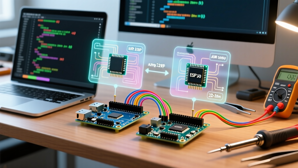
As of 2026, the silicon supply chain has stabilized, and the cost gap between 8-bit AVR chips and 32-bit alternatives has narrowed significantly. If your application requires complex DSP, wireless connectivity, or high-speed USB, treating the Arduino IDE as a software ecosystem while migrating to a more capable microcontroller is the optimal upgrade path.
| Microcontroller | Architecture & Speed | Approx. BOM Cost (Low Vol) | Key Migration Advantage | Hidden PCB Costs |
|---|---|---|---|---|
| ATmega328P-AU | 8-bit AVR @ 16MHz | $2.15 | Massive legacy library support, low sleep current (µA range). | Requires external crystal, 5V LDO if USB powered. |
| Raspberry Pi RP2040 | Dual-core ARM Cortex-M0+ @ 133MHz | $0.80 (MCU) + $0.35 (Flash) | PIO state machines for custom protocols, native USB. | Requires external QSPI flash (e.g., W25Q16JV), complex boot circuit. |
| ESP32-S3-WROOM-1 | Dual-core Xtensa LX7 @ 240MHz | $2.80 (Module) | Integrated Wi-Fi/BLE, AI vector instructions, embedded flash. | High deep-sleep current compared to AVR, requires RF matching network if using raw chip. |
Upgrading to the RP2040 Ecosystem
The RP2040 has become the premier upgrade path for makers migrating from the ATmega328P. While the raw chip costs less than a dollar, it lacks internal non-volatile memory. You must pair it with an external SPI flash chip. The RP2040 Hardware Design Guide mandates a 100nF decoupling cap on every VREG pin and a specific 1kΩ pull-up on the QSPI CS line to prevent boot failures. The Arduino IDE supports the RP2040 natively via the official Arduino Mbed core or the community-driven Earle Philhower core, allowing you to port your existing AVR C++ code with minimal refactoring.
Phase 5: PCB Layout Rules for Mixed-Signal Stability
When laying out your custom PCB, the physical placement of components dictates the reliability of your analog sensors. The ATmega328P features a dedicated ADC (Analog-to-Digital Converter) that is highly sensitive to digital switching noise.
- Split Ground Planes (or Strategic Routing): If using a 2-layer PCB, avoid running high-speed digital traces (like SPI clocks or PWM signals) directly under the ADC input traces. Route analog signals over a solid, unbroken ground plane.
- AVCC Isolation: The ATmega328P has separate VCC and AVCC pins. Connect AVCC to the main 5V or 3.3V rail through a ferrite bead (e.g., 600Ω @ 100MHz) and place a dedicated 100nF capacitor and a 1µF capacitor on the AVCC pin to filter out high-frequency digital noise generated by the CPU core.
- Thermal Relief on Vias: When routing power to the TQFP-32 pads, use thermal relief spokes on vias. Direct copper pours to ground pins without thermal relief will act as heatsinks during hand soldering or reflow, leading to cold solder joints and intermittent connectivity.
Final Deployment Checklist
Before sending your Gerber files to the fabricator, verify the following migration checkpoints:
- Bootloader matches the selected clock source (16MHz external vs 8MHz internal).
- BOD fuse bits are configured for your specific power supply's voltage droop characteristics.
- DTR auto-reset capacitor (100nF) is present if serial programming is required post-assembly.
- ICSP test points or headers are exposed for initial firmware flashing and unbricking.
- AVCC is properly filtered and connected; floating AVCC will result in a non-functional chip even if digital I/O appears to work.
By treating the Arduino ecosystem as a software framework rather than a hardware crutch, you can seamlessly migrate from bulky development boards to highly optimized, production-grade microcontroller deployments.