
Decoding the ESP32S Pinout: Beyond the Silkscreen
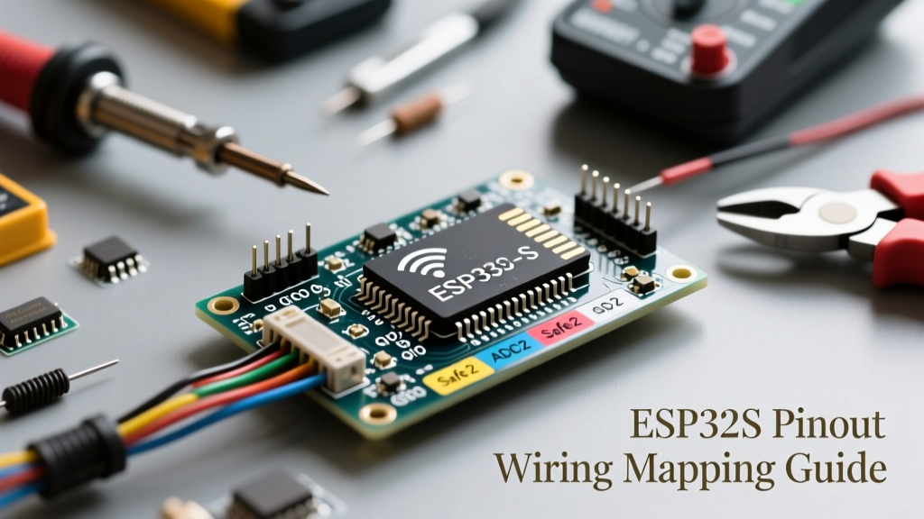
When makers and engineers search for the esp32s pinout, they are typically referring to the ubiquitous NodeMCU-32S or the standard 30-pin ESP32 DevKit V1. While the Espressif ESP32 microcontroller is an absolute powerhouse for IoT and edge computing, its pinout is notoriously unforgiving for beginners. Unlike the Arduino Uno, where almost every digital pin behaves predictably, the ESP32 multiplexes its GPIOs across multiple internal peripherals. This architectural complexity leads to silent failures, boot loops, and even hardware damage if the pins are misconfigured.
In this comprehensive how-to tutorial, we will move past the basic silkscreen labels and dive deep into the silicon-level realities of the ESP32S. We will cover the three fatal wiring traps that destroy projects and walk through a practical sensor wiring tutorial.
The Definitive ESP32S GPIO Capability Matrix
Not all pins on the ESP32S DevKit are created equal. Some are strictly inputs, some are tied to the internal flash memory, and others possess unique analog capabilities. Below is a functional matrix detailing the hidden constraints of the standard 30-pin form factor.
| GPIO Pin | Primary Function | Safe for General Use? | Hidden Constraints & Notes |
|---|---|---|---|
| GPIO 0 | Boot / PWM | No (with caveats) | Strapping pin. Must be HIGH on boot for normal execution. Pulled LOW to enter flash mode. |
| GPIO 2 | Boot / LED | No (with caveats) | Strapping pin. Must be LOW or floating to boot. Often connected to the onboard blue LED. |
| GPIO 4 | Touch0 / ADC2 | Yes | Excellent for capacitive touch interrupts. Avoid if using WiFi and needing ADC simultaneously. |
| GPIO 12 | Touch5 / ADC2 | Dangerous | MTDI Strapping pin. If pulled HIGH on boot, it switches internal flash LDO to 1.8V, causing 3.3V SPI flash to fail. |
| GPIO 34-39 | ADC1 / Input Only | Yes | Strictly INPUT pins. No internal pull-up/pull-down resistors. Safe for analog sensing with WiFi active. |
How-To: Navigating the 3 Fatal ESP32 Wiring Traps
To master the esp32s pinout, you must understand what the silicon is doing behind the scenes. Here are the three most common hardware traps and how to engineer your way around them.
Trap 1: The ADC2 vs. WiFi Hardware Conflict
The ESP32 features two Analog-to-Digital Converters: ADC1 and ADC2. A common mistake is wiring an analog sensor (like a light-dependent resistor or soil moisture probe) to an ADC2 pin (GPIO 0, 2, 4, 12, 13, 14, 15, 25, 26, 27) while simultaneously using WiFi. According to the ESP-IDF GPIO API Reference, the WiFi driver requires ADC2 for internal RF calibration and power management. If you call WiFi.begin(), the WiFi stack takes exclusive hardware control of ADC2. Any subsequent calls to analogRead() on an ADC2 pin will silently fail or return garbage data.
The Fix: Always route analog sensors requiring WiFi telemetry to ADC1 pins (GPIO 32, 33, 34, 35, 36, 39). Remember that GPIO 34-39 are input-only and lack internal pull-up resistors, requiring external biasing if necessary.
Trap 2: Strapping Pins and the 'Boot Loop of Death'
Strapping pins dictate the ESP32's boot mode and internal voltage configurations. While GPIO 0 and GPIO 2 are well-known for controlling flash mode vs. normal boot, GPIO 12 (MTDI) is the silent killer. GPIO 12 determines the voltage of the internal LDO that powers the external SPI flash chip. If GPIO 12 is pulled HIGH during reset, the ESP32 configures the LDO to output 1.8V. However, 99% of DevKit boards use 3.3V SPI flash. Supplying 3.3V flash with 1.8V logic levels results in a failure to read the firmware, causing an endless boot loop.
The Fix: Never use GPIO 12 as an output for relays or motors, and never place a pull-up resistor on it. If you must use it, ensure it is pulled LOW or left floating during the first 100ms of boot.
Trap 3: Exceeding the AMS1117 3.3V Regulator Bottleneck
Looking at the power pins on the esp32s pinout, you will see VIN, 5V, and 3V3. The 3V3 pin is the output of the onboard voltage regulator (typically an AMS1117-3.3). While the datasheet for the AMS1117 claims a 1A maximum output, the tiny SOT-223 package on clone boards lacks adequate copper pours for heat dissipation. Pushing more than 400mA-500mA continuously will cause thermal shutdown or silicon degradation.
The Fix: If your project involves NeoPixel strips, GSM modules (like the SIM800L), or high-draw sensor arrays, bypass the onboard regulator. Wire a dedicated external buck converter (like an LM2596) to step down 5V to 3.3V, and tie the grounds together.
Practical Tutorial: Wiring a Low-Power Touch-Activated Sensor Node
Let us apply this knowledge to build a robust, touch-activated environmental monitor using a BME280 I2C sensor and the ESP32's internal capacitive touch peripheral.
Step 1: Map the I2C Bus
The default I2C pins for the ESP32 in the Arduino IDE are GPIO 21 (SDA) and GPIO 22 (SCL). These pins are safe, general-purpose, and do not conflict with WiFi or boot strapping. Wire your BME280 VCC to 3V3, GND to GND, SDA to 21, and SCL to 22.
Step 2: Implement the Touch Wake Interrupt
Instead of using a mechanical button (which requires debouncing and external pull-ups), we will use GPIO 4 (Touch0). Wire a simple copper pad or aluminum foil to GPIO 4 via a 10k ohm resistor for ESD protection.
Pro-Tip: The ESP32 touch peripheral measures capacitance changes. When a finger approaches the copper pad, the capacitance increases, and the touch reading drops. You can configure the Touch Wake API to pull the ESP32 out of deep sleep using almost zero microamps.
Step 3: Firmware Logic (Arduino C++)
In your sketch, initialize the Wire library on pins 21 and 22. Use touchRead(4) to establish a baseline threshold. When the value drops below your threshold, wake the I2C bus, sample the BME280, transmit via WiFi (using ADC1 for any battery voltage monitoring on GPIO 35), and return to deep sleep.
Authoritative References & Further Reading
To continue mastering microcontroller architectures, always consult the primary silicon documentation rather than relying solely on third-party wikis. For advanced multiplexing and peripheral mapping, refer to the Official Espressif ESP32 Datasheet. Additionally, the Random Nerd Tutorials ESP32 Pinout Reference provides excellent visual schematics for the DevKit V1 and NodeMCU-32S variants.
By respecting the hardware constraints of the esp32s pinout, you transition from simply copying tutorials to engineering resilient, production-ready IoT hardware.