
The Anatomy of ESP32 UART Timing Failures
When working with the ESP32, few things are as frustrating as flashing your code to an ESP32-DevKitC or NodeMCU-32S, opening the serial monitor at 115200 baud, and being greeted by a wall of ????? or scrambled Wingdings. You check your wiring, you verify your baud rate settings, and you restart the IDE, but the issue persists. More maddeningly, the UART often works perfectly during early boot, only to fail the moment you initialize the Wi-Fi radio, or it refuses to output anything immediately after waking from deep sleep. This is a classic clock tree misconfiguration.
Understanding the underlying UART clock source for ESP32 dev module environments is critical for stable serial communication. Many developers frantically search for 'uart clock source for esp32 deve module' when encountering these exact baud rate anomalies, often missing the fundamental architecture of the ESP32's power management system.
APB vs. REF_TICK: The Root of Baud Rate Drift
The ESP32’s UART peripheral does not possess its own dedicated, independent crystal oscillator. Instead, it derives its timing from the system’s internal clock tree. By default, both the Arduino core and ESP-IDF configure the UART to use the APB (Advanced Peripheral Bus) clock. Under normal, active conditions, the APB clock runs at a stable 80 MHz.
However, the ESP32 is engineered for aggressive power management. When the CPU frequency scales down to save power, or when the Wi-Fi/Bluetooth modem enters sleep states (such as Wi-Fi Modem Sleep), the APB clock can dynamically scale down to 40 MHz or shut off entirely to conserve energy. The UART baud rate generator relies on a divisor calculated against the APB clock. If your divisor was calculated based on an 80 MHz APB clock, and the APB suddenly drops to 40 MHz, your actual baud rate is instantly halved. Your 115200 baud transmission becomes a 57600 baud transmission, resulting in immediate framing errors and garbage data on the receiving end.
To combat this, Espressif provides an alternative clock source: the REF_TICK clock. The REF_TICK is a highly stable 1 MHz clock derived from the main crystal, specifically designed to remain active and mathematically consistent regardless of CPU frequency scaling or Wi-Fi power save modes.
Diagnostic Matrix: Identifying Your Clock Source Failure
Use the following diagnostic matrix to pinpoint whether your clock configuration is the root cause of your serial errors.
| Symptom | System State | Probable Culprit | Required Fix |
|---|---|---|---|
| Garbage output after Wi-Fi init | Wi-Fi Modem Sleep Active | APB clock scaling down to 40MHz | Switch UART to REF_TICK |
| Serial works, then dies randomly | CPU Frequency Scaling (e.g., 240MHz to 80MHz) | APB clock tied to CPU clock divider | Lock APB clock or use REF_TICK |
| No output after Deep Sleep wake | Waking from Deep Sleep / RTC Reset | APB clock not yet initialized during early boot | Use LP_UART with RTC clock |
| Slight baud rate mismatch (1-2%) | Active mode, no Wi-Fi | Integer division error in UART_CLKDIV_REG | Enable UART fractional divider |
Step-by-Step Resolution in Arduino and ESP-IDF
Resolving these timing anomalies requires explicitly declaring your clock source at the driver level. The method varies depending on whether you are using the Arduino IDE or the native ESP-IDF framework.
Forcing REF_TICK in the Arduino IDE
The Arduino ESP32 core abstracts much of the hardware layer, but you can still access the underlying ESP-IDF driver functions. If you are experiencing baud rate drift when Wi-Fi connects, you need to reconfigure the UART peripheral immediately after Serial.begin().
#include <driver/uart.h>
#include <soc/uart_reg.h>

void setup() {
  Serial.begin(115200);
  // Force UART0 to use the 1MHz REF_TICK clock
  // This prevents baud rate drift during Wi-Fi modem sleep
  uart_set_clk_src(UART_NUM_0, UART_SCLK_REF_TICK);
}
By invoking uart_set_clk_src(), you decouple the UART timing from the volatile APB bus. Note that because REF_TICK is only 1 MHz, the maximum reliable baud rate is mathematically limited. While you can technically push it higher, it is highly recommended to stay at or below 115200 baud when using REF_TICK to avoid sampling errors and bit-width truncation.
ESP-IDF Configuration via Menuconfig
For professional firmware development using ESP-IDF, the clock source can be managed globally via the configuration menu. Navigate to idf.py menuconfig, then follow this path: Component config → Hardware Settings → UART Configuration. Here, you can set the default UART clock source. According to the official Espressif UART API documentation, selecting the appropriate source based on your power profile is mandatory for certification-grade firmware.
Architectural Differences in ESP32-S3 and ESP32-C3
It is vital to note that the clock tree changes significantly in newer Espressif silicon. If you are migrating from the original dual-core ESP32 to the RISC-V based ESP32-C3 or the Xtensa LX7 based ESP32-S3, the REF_TICK concept is largely replaced by direct XTAL or RTC clock routing.
On the ESP32-C3, the UART can be clocked directly from the 40 MHz XTAL or the RTC clock domain. This provides much higher resolution than the 1 MHz REF_TICK while maintaining stability during Wi-Fi sleep states. When diagnosing errors on these newer modules, ensure your ESP-IDF target is correctly set, as applying ESP32-specific APB workarounds to an ESP32-C3 will result in compilation errors or silent register failures.
Deep Sleep and the LP_UART Caveat
When diagnosing UART failures that occur specifically after a deep sleep wake cycle, the standard UART0 and UART1 peripherals are entirely unhelpful. During deep sleep, the digital core (and thus the APB and REF_TICK clocks) is powered off completely.
If you need to output debug logs immediately upon waking from deep sleep—before the system has time to boot the digital core and stabilize the main clocks—you must use the LP_UART (Low Power UART, typically mapped to UART2 on the original ESP32).
Expert Diagnostic Tip: The LP_UART can be clocked directly by the RTC 8 MHz or 150 kHz oscillator. Because the RTC domain remains powered during deep sleep, the LP_UART can transmit the wake-up cause and initial sensor readings before the main CPU even finishes its boot sequence. If your wake-up logs are missing, verify you are routing your debug output to UART2 and configuring it for the RTC clock source, not the APB.
Hardware-Level Verification with an Oscilloscope
Software diagnostics can only tell you what the registers are set to; they cannot confirm the physical reality of the silicon. When dealing with persistent anomalies, you must validate the signal physically.
Measuring the Bit Width Drift
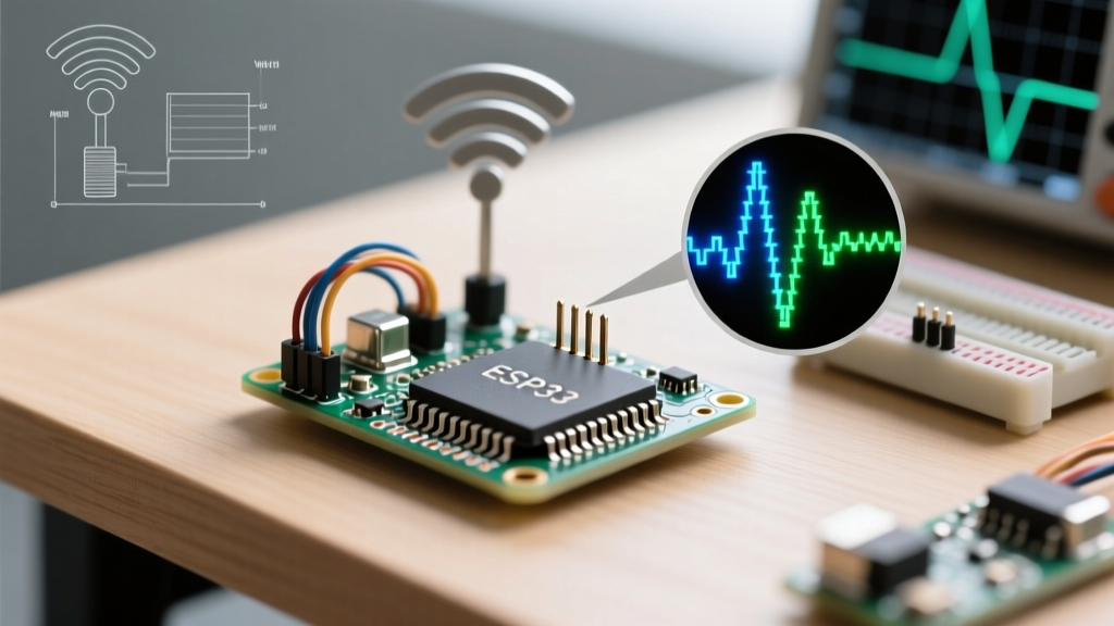
Connect your oscilloscope probe to the TX pin of your ESP32 development board (e.g., GPIO1 on the ESP32-DevKitC). Set your trigger to capture a falling edge on the serial line. At a configured baud rate of 115200, a single bit duration should measure exactly 8.68 microseconds (1 / 115200).
- Scenario A: You measure 8.68 μs before Wi-Fi connects, but it shifts to 17.36 μs after Wi-Fi connects. This confirms your APB clock has halved to 40 MHz, and your UART divisor is static. Switch to REF_TICK immediately.
- Scenario B: You measure 8.75 μs consistently. This indicates a fractional divider limitation. The ESP32 UART baud rate generator uses an integer divider and a fractional component. If the fractional component is truncated in older Arduino core versions, you will see a slight drift that causes errors on highly sensitive USB-to-Serial adapters like the FT232RL or CH340.
For a deeper dive into how power management interacts with peripheral clocks, review the ESP-IDF Sleep Modes documentation, which details exactly which clock domains remain active during various sleep states.
Summary of Best Practices
Diagnosing UART errors on the ESP32 requires looking beyond basic wiring and baud rate matching. You must understand the underlying clock tree and how it interacts with the radio subsystem.
- Use APB only when the ESP32 is plugged into wall power, Wi-Fi is disabled or in constant active mode, and CPU frequency is locked at 240MHz or 160MHz.
- Use REF_TICK (or XTAL on C3/S3) for any battery-powered application utilizing Wi-Fi Modem Sleep, Light Sleep, or dynamic CPU frequency scaling.
- Use the RTC Clock via LP_UART for deep sleep wake-up debugging and ultra-low-power logging.
By aligning your UART clock source with your application's power state, you will permanently eliminate the dreaded serial garbage output and ensure robust, reliable communication in your embedded designs.