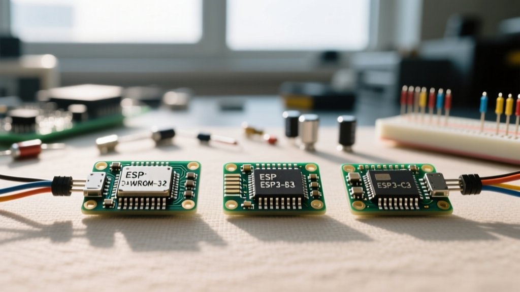

The Espressif ecosystem has expanded far beyond the original dual-core chip, leading to a fragmented but incredibly powerful landscape of ESP32 modules. Whether you are designing a custom PCB, troubleshooting a dev board, or selecting the right System-on-Chip (SoC) for a low-power IoT sensor, navigating the differences between the WROOM, S3, C3, C6, and H2 variants can be overwhelming.
This quick reference guide and FAQ is designed for electrical engineers, makers, and firmware developers who need immediate, actionable answers regarding hardware quirks, pinout traps, and Arduino IDE configurations for modern ESP32 modules.
The Ultimate ESP32 Modules Comparison Matrix
Before diving into troubleshooting, it is critical to select the right module for your application. Espressif has segmented their lineup based on processing needs, AI capabilities, and wireless protocols.
| Module Family | Core Architecture | Wireless Protocols | Key Differentiator | Best Use Case |
|---|---|---|---|---|
| ESP32-WROOM-32E | Xtensa Dual-Core 32-bit LX6 | WiFi 4, Classic BT, BLE 4.2 | Legacy support, high GPIO count | General IoT, audio streaming, legacy replacements |
| ESP32-S3-WROOM-1 | Xtensa Dual-Core 32-bit LX7 | WiFi 4, BLE 5.0 | Vector instructions for AI, Native USB OTG | Machine Learning (TinyML), HMI displays, USB devices |
| ESP32-C3-MINI-1 | RISC-V Single-Core 32-bit | WiFi 4, BLE 5.0 | Low cost, pin-compatible with ESP8266 | Cost-sensitive smart home, basic sensors |
| ESP32-C6-WROOM-1 | RISC-V Single-Core (160MHz) | WiFi 6, BLE 5.0, 802.15.4 | WiFi 6 Target Wake Time (TWT), Zigbee/Thread | Battery-operated Matter devices, low-power mesh |
| ESP32-H2-MINI-1 | RISC-V Single-Core (96MHz) | BLE 5.0, 802.15.4 (No WiFi) | Ultra-low power, dedicated Thread/Zigbee | Matter end-nodes, smart lighting, mesh sensors |
Why Won't My Custom Board Boot? (Strapping Pin FAQs)
One of the most frequent hardware failures when designing custom boards with bare ESP32 modules involves strapping pins. These pins are sampled during the reset sequence to determine the boot mode and flash voltage.
The GPIO 12 (MTDI) Flash Voltage Trap
On the original ESP32 and ESP32-S3, GPIO 12 dictates the internal VDD_SDIO voltage. If GPIO 12 is pulled HIGH during boot, the internal regulator switches to 1.8V. Since most standard SPI flash chips require 3.3V, this will cause the module to brownout or fail to read the flash, resulting in a boot loop.
Quick Fix: Ensure GPIO 12 is either left floating or pulled LOW via a 10kΩ resistor if you are using a standard 3.3V SPI flash chip. Consult the Espressif ESP32 Datasheet for the exact strapping pin matrix of your specific SoC variant.
GPIO 0 and the Bootloader Mode
GPIO 0 must be HIGH for normal execution and LOW to enter the serial bootloader. If your external circuitry (like a sensor or motor driver) pulls GPIO 0 low during power-up, the module will stall in download mode. Always use a pull-up resistor on GPIO 0 and ensure peripheral devices do not drive this pin low on startup.
ADC Readings Are Erratic: What's Wrong?
The Analog-to-Digital Converter (ADC) on ESP32 modules is notorious for non-linearity and noise if not configured correctly in the Arduino IDE or ESP-IDF.
Why is ADC2 Unusable with WiFi?
On the classic ESP32, the ADC2 peripheral is shared with the WiFi subsystem. If WiFi is enabled, ADC2 readings will fail or return garbage data. Solution: Always route analog sensors to ADC1 pins (GPIO 32-39) if your application requires simultaneous WiFi transmission.
Understanding Attenuation and Usable Ranges
The ESP32 ADC is 12-bit (0-4095), but the input voltage range is dictated by the attenuation setting. Pushing 3.3V into a 0dB channel will saturate the reading and cause permanent non-linearity at the upper bounds.
- 0 dB attenuation: Usable range 100mV – 950mV
- 2.5 dB attenuation: Usable range 100mV – 1250mV
- 6 dB attenuation: Usable range 150mV – 1750mV
- 11 dB attenuation: Usable range 150mV – 2450mV (Default in Arduino)
Note: Even at 11dB, the ESP32 cannot safely read a full 3.3V without an external voltage divider. Furthermore, the ADC is highly non-linear below 150mV. Use an external op-amp or dedicated ADC (like the ADS1115) for precision millivolt measurements.
Flash Memory Modes: QIO vs. DIO Explained
When compiling sketches in the Arduino IDE, you are presented with Flash Mode options: QIO, QOUT, DIO, and DOUT. Selecting the wrong mode can result in a bricked-feeling module that fails to execute code.
What do these acronyms mean?
- DIO (Dual I/O): Uses 2 data lines for communication. Slower but highly robust against poor PCB signal integrity.
- QIO (Quad I/O): Uses 4 data lines. Significantly faster boot and execution times, but requires pristine RF/high-speed PCB routing.
Why does QIO fail on some clone boards?
Cheap third-party ESP32 dev boards often use substandard PCB traces and lack proper ground referencing for the SPI lines. At 80MHz QIO mode, signal reflection and crosstalk cause bit errors during flash reads, leading to Guru Meditation errors or continuous reboots. If you are using a budget module and experiencing random crashes, switch the Arduino IDE Flash Mode to DIO and drop the Flash Frequency to 40MHz.
RF Layouts: Trace Antenna vs. U.FL Connector
Designing the RF section of an ESP32 module is where most custom hardware projects fail certification or suffer from terrible range. Espressif modules generally come in two flavors: PCB Trace antennas and IPEX/U.FL connectors.
The Keep-Out Zone Mandate
If you select a module with an onboard PCB trace antenna, the area directly beneath and immediately surrounding the antenna trace on your motherboard must be completely clear. This means no ground planes, no signal traces, and no components on any layer directly under the antenna overhang. Violating this keep-out zone detunes the antenna impedance, dropping your range from 50 meters to 2 meters. Refer to the Espressif Hardware Design Guidelines for exact dimensional keep-out diagrams.
When to use an IPEX/U.FL Connector
Choose the U.FL variant if your product will be housed in a metal enclosure, or if you need to route the antenna to the outside of a dense PCB stack. Be aware that U.FL connectors are rated for only 30 mating cycles; they are not meant for frequent field swapping.
Arduino IDE Upload Failures: Quick Fixes
Firmware developers frequently encounter the dreaded Failed to connect to ESP32: Timed out waiting for packet header error. This is almost always a hardware auto-reset circuit failure, not a software bug.
The 10µF Capacitor Trick
The Arduino IDE relies on the DTR and RTS serial lines to toggle the EN (Enable) and GPIO 0 pins to automatically enter the bootloader. On many custom boards or cheap clones, the parasitic capacitance on the EN line is too low, causing the chip to wake up too fast before the serial bridge is ready.
The Fix: Solder a 10µF electrolytic or tantalum capacitor between the EN pin and GND. This slows the rising edge of the EN pin just enough to allow the USB-to-UART bridge to establish the bootloader handshake. For more on framework-level configurations and board definitions, check the Arduino ESP32 Core GitHub repository.
Manual Bootloader Entry
If the capacitor trick fails, you must force the module into download mode manually: 1. Press and hold the BOOT button (pulls GPIO 0 LOW). 2. Press and release the EN/RST button. 3. Release the BOOT button. 4. Click 'Upload' in the Arduino IDE.
Summary Checklist for ESP32 Hardware Design
- Verify strapping pins (especially GPIO 12) are not conflicted by external sensors.
- Route all critical analog sensors to ADC1 pins.
- Use voltage dividers for 3.3V ADC measurements; do not rely on internal attenuation for precision.
- Maintain strict ground-plane keep-out zones under PCB trace antennas.
- Include a 10µF capacitor on the EN line for reliable auto-reset programming.