
The Hardware Reality: Identifying Your DOIT Variant
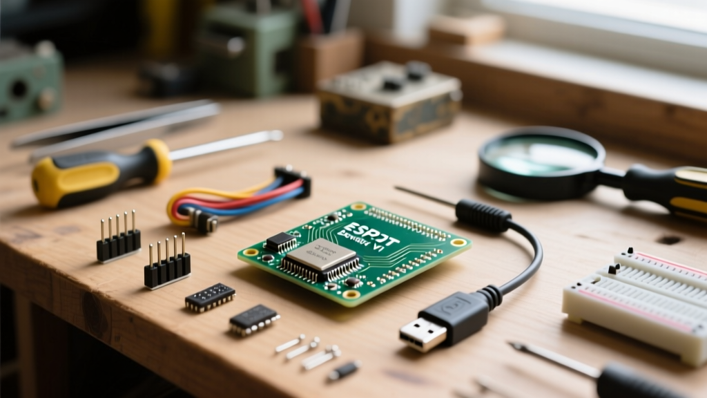
The DOIT ESP32 DEVKIT V1 is arguably the most ubiquitous third-party development board in the maker community. However, treating all DOIT boards as identical is the first mistake that derails an optimized workflow. Before writing a single line of code, you must identify the specific hardware revision sitting on your desk, as this dictates your driver setup and physical prototyping constraints.
Historically, the original DOIT ESP32 DEVKIT V1 boards were manufactured with 30 pins and utilized the Silicon Labs CP2102 USB-to-UART bridge. As supply chains shifted and the board became massively popular, a 38-pin variant emerged, frequently swapping the CP2102 for the WCH CH340C chip to reduce costs. This distinction is critical: installing the wrong virtual COM port driver will result in silent failures or 'port not found' errors in the Arduino IDE, wasting hours of debugging time. Always inspect the metallic chip situated directly behind the micro-USB port. If it is a square QFN package labeled CP2102, use the official Silicon Labs drivers. If it is a rectangular SOIC-16 package labeled CH340, source the latest WCH drivers.
Streamlining the Arduino IDE Environment
Workflow optimization in the Arduino IDE hinges on reducing compile times and managing flash memory partitions efficiently. When using the Random Nerd Tutorials ESP32 Setup guide as a baseline, ensure you are pulling the latest Espressif core via the Board Manager URL. For the DOIT board, always select 'DOIT ESP32 DEVKIT V1' from the board list rather than the generic 'ESP32 Dev Module'. The DOIT profile includes pre-configured parameters for the board's specific auto-reset circuitry, which we will discuss later.
Partition Scheme Selection
By default, the IDE assigns a 'Default 4MB with spiffs' partition scheme. If your workflow involves heavy OTA (Over-The-Air) updates or large web server assets, you must manually adjust this. Switching to 'Minimal SPIFFS (1.9MB App with OTA/190KB SPIFFS)' prevents the dreaded 'Sketch too big' compilation error and streamlines the deployment of IoT dashboards directly from the ESP32's internal filesystem.
Flashing Bottlenecks and the Auto-Reset Quirk
Nothing destroys momentum faster than a failed upload. The DOIT ESP32 DEVKIT V1 features a hardware auto-reset circuit utilizing two NPN transistors (typically marked Q1 and Q2) that manipulate the EN (Enable) and GPIO0 pins via the DTR and RTS serial signals. This is designed to automatically trigger the bootloader without manual intervention.
However, a known timing mismatch between the Windows 10/11 USB CDC drivers and the DOIT transistor switching speed often causes the IDE to hang indefinitely on the 'Connecting...' status. To optimize your flashing workflow and bypass this hardware quirk, implement the following protocol:
- Maximize Baud Rate: In the Arduino IDE Tools menu, change the Upload Speed from the default 115200 or 460800 to 921600. The ESP32's UART and the CP2102/CH340 chips can easily handle this, reducing a 1.2MB sketch flash time from roughly 45 seconds down to 12 seconds.
- The Manual Override Dance: If the IDE hangs on 'Connecting...', do not cancel the upload. Instead, press and hold the 'BOOT' button on the DOIT board for exactly one second, then release. This manually forces GPIO0 low while the EN pin resets, cleanly catching the bootloader window and allowing the 921600 baud upload to proceed instantly.
Build Environment Comparison: Arduino IDE vs. PlatformIO
For professional makers and engineers iterating rapidly on complex ESP32 firmware, migrating from the Arduino IDE to PlatformIO (via VS Code) represents a massive workflow upgrade. PlatformIO handles dependencies, C++ IntelliSense, and multi-file project structures far more elegantly. Below is a comparative analysis of workflow metrics when targeting the DOIT ESP32 DEVKIT V1.
| Metric | Arduino IDE 2.x | PlatformIO (VS Code) |
|---|---|---|
| Initial Clean Compile Time | ~45 seconds | ~28 seconds (Parallel build) |
| Incremental Compile Time | ~12 seconds | ~3 seconds (Ninja build system) |
| Library Management | Global (Risk of version conflicts) | Project-isolated (platformio.ini) |
| Board Definition | DOIT ESP32 DEVKIT V1 | board = esp32doit-devkit-v1 |
For deep technical specifications on the PlatformIO board definition, refer to the PlatformIO DOIT ESP32 DevKit V1 Documentation. Utilizing PlatformIO allows you to define custom build flags and partition tables directly in your repository, ensuring your CI/CD pipeline or team members never face environment drift.
Breadboard Ergonomics and Pinout Management
A major physical workflow hindrance of the DOIT ESP32 DEVKIT V1 is its width. The 30-pin and 38-pin variants are just wide enough that when plugged into a standard 830-tie-point solderless breadboard, the pins align with the outer power rails, leaving zero accessible GPIO holes for jumper wires. This forces makers into awkward wiring workarounds that lead to loose connections and debugging nightmares.
The Dual-Breadboard Hack: The optimal physical workflow is to use two breadboards placed side-by-side. Remove the power rail from one edge of each board and snap them together. This provides the necessary width to accommodate the DOIT board while leaving one full row of GPIO access on each side.
Navigating Strapping Pins
When designing your circuit on the breadboard, you must account for the ESP32's strapping pins. These pins dictate the boot mode of the ESP-WROOM-32 module upon power-up or reset. Accidentally pulling these pins high or low via external sensors or relays will cause the DOIT board to boot into flash-download mode or fail to execute your sketch entirely. Consult the Espressif System API and Strapping Pins documentation for the silicon-level reasoning behind this behavior.
| GPIO Pin | Boot Mode Impact | Workflow Recommendation |
|---|---|---|
| GPIO 0 | Determines SPI boot vs. Download mode | Avoid external pull-downs; use for input only with internal pull-up. |
| GPIO 2 | Must be LOW or floating to boot from SPI flash | Never connect to an active-high relay or LED on startup. |
| GPIO 12 (MTDI) | Selects flash voltage (1.8V vs 3.3V) | Keep floating or LOW. Pulling HIGH will brownout the 3.3V regulator. |
| GPIO 15 (MTDO) | Controls boot log printing | Safe for general I/O after boot sequence completes. |
Power Delivery Profiling
Finally, an optimized workflow requires understanding the power limitations of the DOIT board's onboard voltage regulation. The board features an AMS1117-3.3 linear regulator. While the datasheet for the AMS1117 claims an 800mA maximum output, the DOIT board's PCB copper pour acts as a very poor heatsink. In real-world thermal testing, drawing more than 450mA continuously from the 3.3V pin will cause the regulator to thermally throttle, resulting in brownouts and random ESP32 reboots.
If your project involves power-hungry peripherals like NeoPixel LED strips, SIM800L GSM modules, or multiple active relays, bypass the onboard regulator entirely. Wire your high-current peripherals directly to the 5V VIN pin (or an external 5V supply sharing a common ground), and use logic-level MOSFETs to switch the loads via the ESP32's 3.3V GPIO signals. This preserves the integrity of the DOIT board's 3.3V rail, ensuring stable Wi-Fi and Bluetooth RF performance without voltage sag.
Conclusion
Mastering the ESP32 DevKit V1 DOIT is less about memorizing code and more about optimizing the physical and digital environment around the microcontroller. By correctly identifying your USB-UART bridge, leveraging high-baud-rate flashing with manual bootloader overrides, migrating to PlatformIO for complex projects, and respecting the physical strapping pin and power constraints, you transform the DOIT board from a frustrating prototyping bottleneck into a highly reliable engine for IoT development.