
The Anatomy of an ESP32 Device: Choosing Your Silicon
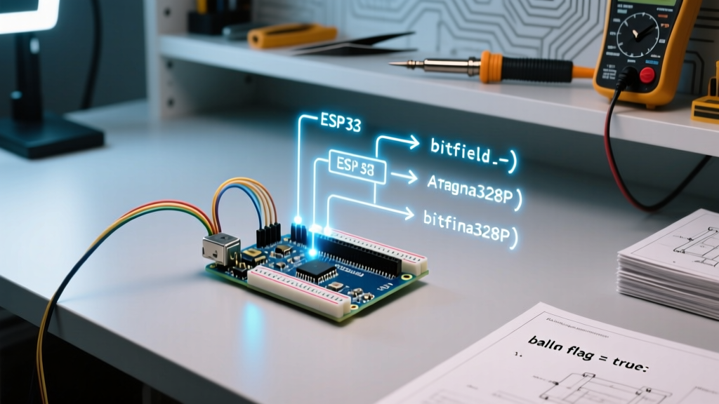
Before configuring your development environment, you must understand the specific silicon inside your ESP32 device. The term "ESP32" refers to a broad family of System-on-Chips (SoCs) developed by Espressif Systems. Selecting the wrong board profile in your IDE will lead to immediate compilation errors or, worse, silent runtime failures in RF calibration.
| SoC Variant | Cores / Architecture | Wireless | Native USB | Best For |
|---|---|---|---|---|
| ESP32 (Classic) | Dual-core Xtensa LX6 | Wi-Fi 4, BT/BLE 4.2 | No | General IoT, legacy projects |
| ESP32-S3 | Dual-core Xtensa LX7 | Wi-Fi 4, BLE 5.0 | Yes (OTG) | AI/Edge ML, USB HID devices |
| ESP32-C3 | Single-core RISC-V | Wi-Fi 4, BLE 5.0 | Yes (Serial/JTAG) | Low-cost, pin-compatible 8266 replacements |
When configuring your ESP32 device, always verify the exact module printed on the RF shield (e.g., ESP32-WROOM-32E vs. ESP32-WROVER-IE). WROVER modules include external PSRAM, which requires enabling the "PSRAM: Enabled" flag in your board configuration to prevent memory allocation panics when using large buffers or audio processing.
Core Environment Configuration: Arduino IDE vs. PlatformIO
The Arduino core for the ESP32 is maintained by the community and Espressif engineers. To configure the Arduino IDE, navigate to File > Preferences and add the official board manager URL:
https://raw.githubusercontent.com/espressif/arduino-esp32/gh-pages/package_esp32_index.jsonWhile the Arduino IDE is excellent for quick prototyping, professional makers configuring a complex ESP32 device should migrate to PlatformIO. PlatformIO allows granular control over the build flags, partition tables, and framework versions via the platformio.ini file.
Here is a production-grade platformio.ini configuration for an ESP32-WROVER device requiring OTA updates and PSRAM:
[env:esp32dev]
platform = espressif32@6.5.0
board = esp-wrover-kit
framework = arduino
board_build.partitions = min_spiffs.csv
build_flags =
    -DBOARD_HAS_PSRAM
    -mfix-esp32-psram-cache-issue
upload_speed = 921600
monitor_speed = 115200
Notice the -mfix-esp32-psram-cache-issue flag. This is a critical compiler flag for classic ESP32 devices utilizing PSRAM, resolving a known silicon bug where cache access to external RAM causes data corruption under specific interrupt loads.
Resolving the "Timed Out" Bootloader Failure Mode
The most notorious hurdle when configuring a new ESP32 device is the upload failure. If your serial monitor outputs "Failed to connect to ESP32: Timed out waiting for packet header", your host PC is failing to handshake with the ROM bootloader.
The GPIO0 and EN Circuit
For the ESP32 to enter UART download mode, GPIO0 must be pulled LOW while the EN (CHIP_PU) pin is pulsed LOW then HIGH. Many cheap clone development boards omit the necessary 10µF electrolytic capacitor on the EN line or the 0.1µF capacitor on GPIO0, preventing the auto-reset circuit from functioning.
- Manual Bootloader Entry: Press and hold the "BOOT" button (GPIO0), tap the "EN" button, then release "BOOT".
- Driver Conflicts: Clone boards frequently use the CH340C UART bridge, while premium boards use the CP2102. Ensure you have the official CP210x drivers or the correct CH340 drivers installed, and disable "Prolific" drivers if you are on Windows 11, as they often intercept the COM port.
Flash Memory Partitioning: Beyond the Default Sketch
A standard ESP32 device features 4MB or 8MB of SPI flash memory. By default, the Arduino IDE allocates a massive 1.4MB for the application and leaves the rest for SPIFFS (SPI Flash File System), which is largely deprecated in favor of LittleFS. Furthermore, the default layout leaves zero room for Over-The-Air (OTA) updates.
If you intend to deploy your ESP32 device in the field, you must configure a custom partition table. Below is a comparison of standard partition schemes available in the ESP32 Arduino core:
| Partition Scheme | App Size | OTA Support | File System Size | Use Case |
|---|---|---|---|---|
| Default 4MB | 1.4MB | No | 2.3MB (SPIFFS) | Basic local testing |
| Minimal SPIFFS | 1.9MB | No | 190KB (LittleFS) | Large monolithic firmware |
| OTA (App 2x) | 1.2MB x2 | Yes | 1.2MB | Production IoT deployments |
| Custom (Huge App) | 3MB | No | 1MB | Heavy ML models / Audio |
To implement OTA, you must select a scheme with two app partitions (e.g., app0 and app1). The bootloader will automatically swap execution to the newly flashed partition upon a successful checksum verification.
File System Configuration: Migrating to LittleFS
Historically, makers stored configuration files and web server assets on the ESP32 device using SPIFFS. However, SPIFFS lacks true directory support and is highly susceptible to corruption during unexpected power loss—a common occurrence in DIY IoT deployments. Espressif officially deprecated SPIFFS in favor of LittleFS.
LittleFS is a fail-safe filesystem designed specifically for NOR flash memory. When configuring your project, you must include the FS.h and LittleFS.h libraries. To format and mount the filesystem safely, use the following configuration pattern:
#include "FS.h"
#include "LittleFS.h"
#define FORMAT_LITTLEFS_IF_FAILED true
void initFileSystem() {
  if(!LittleFS.begin(FORMAT_LITTLEFS_IF_FAILED)){
    Serial.println("LittleFS Mount Failed");
    return;
  }
  Serial.printf("Total space: %d bytes\n", LittleFS.totalBytes());
  Serial.printf("Free space: %d bytes\n", LittleFS.freeBytes());
}
By utilizing LittleFS, your ESP32 device will automatically perform wear-leveling and power-loss resilience checks, ensuring your JSON configuration files and SSL certificates survive abrupt power cycles.
Deep Sleep Configuration and RTC Memory Retention
For off-grid sensor nodes, configuring the deep sleep parameters of your ESP32 device is mandatory. In deep sleep, the CPU, RF subsystem, and main RAM are powered down, leaving only the Real-Time Clock (RTC) controller and RTC memory active. The current draw drops from ~80mA to roughly 10µA.
Variables stored in standard SRAM are lost during deep sleep. To retain state data (like a boot counter or sensor calibration offset) across sleep cycles, you must declare them with the RTC_DATA_ATTR attribute:
RTC_DATA_ATTR int bootCount = 0;
void setup() {
  bootCount++;
  Serial.printf("Boot number: %d\n", bootCount);
  // Configure wake up sources (e.g., Timer, External GPIO)
  esp_sleep_enable_timer_wakeup(600 * 1000000ULL); // 10 minutes
  esp_deep_sleep_start();
}
Note that RTC memory is limited to 8KB. Attempting to store large arrays or strings in this region will result in linker errors. Furthermore, waking from an external GPIO pin requires configuring the RTC IO pads before initiating sleep, ensuring the device can reliably detect a button press or PIR sensor trigger while the main SoC is effectively dead.
Advanced RF and Power Configuration Parameters
Configuring an ESP32 device for battery-powered operation requires deep manipulation of the RF modem and power domains. The Wi-Fi modem is the largest current consumer, spiking up to 240mA during transmission bursts.
Disabling the Brownout Detector
When powering an ESP32 device from a marginal USB port or a long, thin wire, the voltage may dip momentarily during Wi-Fi initialization. This triggers the hardware brownout detector, causing an infinite reboot loop with the error: "Brownout detector was triggered". You can disable this in your setup function:
#include "soc/soc.h"
#include "soc/rtc_cntl_reg.h"
void setup() {
  WRITE_PERI_REG(RTC_CNTL_BROWN_OUT_REG, 0); // Disable brownout
  // Rest of initialization
}
Tuning TX Power for Thermal Management
By default, the ESP32 transmits at maximum power (~20dBm). If your device is enclosed in a sealed IP67 junction box, this can cause thermal throttling. You can dynamically scale the RF output power using the Espressif Wi-Fi API:
#include <WiFi.h>
#include <esp_wifi.h>
void reduceTxPower() {
  // Set max TX power to 11dBm (approx 12.5mW)
  esp_wifi_set_max_tx_power(44); // Value is in 0.25dBm steps (44 * 0.25 = 11)
}
Understanding these low-level configurations separates basic hobbyists from embedded engineers capable of deploying robust, field-ready ESP32 hardware.