
Bridging RNT Code and 3DP Hardware
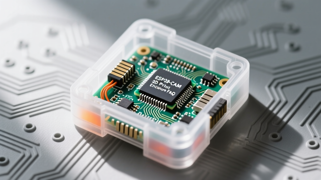
Combining the robust, open-source Arduino IDE sketches from Random Nerd Tutorials (RNT) with custom 3D printed (3DP) enclosures is a rite of passage for advanced makers. Whether you are building a Wi-Fi video streaming server, a Telegram-based face recognition bot, or a low-power PIR-triggered security camera, the software is only half the battle. The physical housing dictates the long-term reliability of your ESP32-CAM module in the field.
However, the intersection of ESP32-CAM hardware, RNT code, and 3DP fabrication is fraught with hidden pitfalls. Thermal throttling, antenna detuning, and optical glare can turn a perfect software prototype into a failing deployment. This quick reference FAQ bridges the gap between Sara Santos' legendary code and practical 3D printing engineering, giving you the exact tolerances, material choices, and troubleshooting frameworks needed for success.
Quick Reference: Filament Selection for ESP32-CAM Enclosures
Not all filaments survive the thermal output of the ESP32 SoC or outdoor UV exposure. Use this matrix to select your 3DP material before slicing your STL files.
| Filament | Glass Transition (Tg) | UV Resistance | Verdict for ESP32-CAM |
|---|---|---|---|
| PLA | ~60°C | Poor | Avoid. Will warp under RNT streaming loads. |
| PETG | ~80°C | Moderate | Good for indoor enclosures and mild outdoor. |
| ABS | ~105°C | Poor | Excellent thermals, but degrades in sunlight. |
| ASA | ~103°C | Excellent | Best overall choice for outdoor security cams. |
| CF-Nylon | ~120°C+ | Good | Overkill, but beware of RF interference. |
Top 5 ESP32-CAM 3DP & RNT Integration FAQs
FAQ 1: Why does my RNT Video Streaming sketch crash inside a 3DP enclosure?
When running the popular RNT ESP32-CAM Video Streaming sketch, the dual-core Xtensa LX6 processor operates at 240MHz while simultaneously encoding JPEG frames from the OV2640 sensor. This pushes the SoC power draw to peaks of 450mA, generating significant localized heat. The ESP32 silicon can easily exceed 75°C in a stagnant, enclosed volume.
If your 3DP enclosure is printed in standard PLA (which has a glass transition temperature of roughly 60°C), the plastic will soften and warp. This warping often physically presses against the fragile OV2640 ribbon cable or the U.FL antenna connector, leading to I2C bus errors, dropped frames, or complete hardware detachment. Solution: Always print ESP32-CAM enclosures in PETG or ASA, and include passive ventilation slots (minimum 2mm width) directly above the SoC and voltage regulator.
FAQ 2: How do I design a 3DP case for the RNT Telegram Face Recognition Bot?
Face recognition relies heavily on consistent lighting and contrast. The standard OV2640 module is highly susceptible to specular highlights and IR interference, which can cause the RNT face detection bounding boxes to fail or trigger false positives. When designing a 3DP enclosure for this specific sketch, you must integrate a physical lens hood.
Model a cylindrical shroud extending exactly 12mm past the OV2640 lens front element, with an internal diameter of 22mm. Print this hood in matte black PLA or PETG to absorb stray light. Additionally, ensure the 3D printed mounting bracket holds the camera PCB perfectly parallel to the target area; even a 5-degree tilt introduced by poorly toleranced 3DP standoffs can skew the facial landmark mapping algorithm used in the Arduino IDE sketch.
FAQ 3: What are the exact 3DP mounting tolerances for the Ai-Thinker module?
The Ai-Thinker ESP32-CAM board measures exactly 40mm x 27mm x 4.5mm (excluding headers and the camera module). The dual rows of 8-pin headers are spaced at a standard 2.54mm pitch, with an inner row-to-row distance of 17.78mm. When designing a friction-fit or snap-fit 3DP enclosure, do not rely on clamping the PCB edges.
Instead, model four cylindrical standoffs (3mm diameter, 4mm height) that align with the four corner mounting holes (which are 2.5mm in diameter). Use M2 or M2.5 self-tapping screws designed for 3D printed plastics. Attempting to squeeze the 27mm width into a tight 27.1mm slot will inevitably bow the PCB, risking micro-fractures in the ceramic capacitors located near the AMS1117 voltage regulator.
FAQ 4: Will a carbon-fiber infused 3DP filament kill my Wi-Fi signal?
Yes. The Ai-Thinker ESP32-CAM utilizes a PCB trace antenna located on the top edge of the board. While standard PLA, PETG, and ABS are virtually transparent to 2.4GHz RF signals, carbon-fiber (CF) infused filaments contain microscopic conductive carbon strands. Printing an enclosure that envelops the antenna region with CF-PETG or CF-Nylon will create a partial Faraday cage, detuning the antenna impedance and dropping your Wi-Fi RSSI by 15 to 30 dBm.
If you require the structural rigidity of carbon fiber filaments, you must model a dedicated 'antenna window' or cutout in the top 15mm of the enclosure, leaving the trace antenna exposed to the air, or cover the cutout with a non-conductive TPU or standard PETG insert.
FAQ 5: How do I prevent the 'Brownout detector was triggered' error in tight 3DP cases?
This notorious Arduino Serial Monitor error is rarely a software bug; it is a physical power delivery failure. RNT sketches initialize the camera with high-power settings (like framesize.FRAME_SVGA), demanding instant current spikes. If your 3DP enclosure features a tight, 90-degree micro-USB cable routing slot, the physical stress on the cable connector increases contact resistance. This resistance causes the 5V rail to sag below 4.8V during camera initialization, triggering the ESP32's internal brownout protection.
Design Rule: Always model a generous cable relief channel (at least 8mm wide and 15mm long) in your 3DP baseplate. Better yet, design the enclosure to accept a bare 5V and GND wire connection via a JST-XH connector, bypassing the fragile micro-USB port entirely and allowing you to power the module directly through the 5V and GND header pins.
Optimizing RNT Sketch Settings for 3DP Constraints
When your 3DP enclosure design prioritizes weatherproofing over ventilation, you must compensate in the Arduino IDE. The standard RNT camera initialization code is optimized for open-air bench testing. If you are sealing the module inside an IP65-rated PETG or ASA box, modify the camera_config_t struct in your sketch to reduce thermal output.
First, adjust the jpeg_quality parameter. While a value of 10 provides pristine images for face recognition, it forces the ESP32 image signal processor (ISP) to work significantly harder, generating excess heat. Bumping this value to 18 drastically reduces SoC load with minimal visible degradation in a 3DP-housed security camera. Second, if your 3DP optical window introduces slight diffraction, avoid using software-based edge enhancement filters in the sketch, as this compounds the processing heat. Finally, implement deep sleep cycles (esp_deep_sleep_start()) in your PIR-triggered RNT sketches to allow the internal ambient temperature of the 3DP enclosure to equalize with the outside air between captures.
Troubleshooting Matrix: RNT Sketch Errors Post-Assembly
Once your ESP32-CAM is sealed inside its 3DP enclosure, new failure modes emerge. Use this quick-reference matrix to diagnose issues that only appear after physical assembly.
- Symptom: Camera initializes, but stream drops after 3 minutes.
3DP Root Cause: Thermal throttling. The AMS1117 regulator is overheating inside a sealed PLA box.
Fix: Apply a 5mm x 5mm x 1mm copper heatsink to the AMS1117 and add cross-flow ventilation slots to the CAD model. - Symptom:
Camera probe failed with error 0x20004on boot.
3DP Root Cause: The 3D printed front plate is pressing against the OV2640 ribbon cable, shorting the exposed traces or bending the FPC connector.
Fix: Increase the internal Z-depth clearance behind the camera module by at least 3mm and add a Kapton tape shield to the ribbon cable. - Symptom: Wi-Fi connects on the bench, but fails when mounted to the wall.
3DP Root Cause: Mounting the 3DP case directly against a concrete or metal-backed drywall surface detunes the ground plane of the PCB antenna.
Fix: Model a 10mm standoff gap between the rear of the enclosure and the mounting surface, or integrate a TPU spacer.
Pro-Tips for Long-Term Field Deployments
For outdoor deployments utilizing RNT's MQTT or Telegram bot sketches, do not rely on 3D printed threads for waterproofing. Model a 2mm channel into the enclosure lip and press-fit a length of 2mm solid silicone O-ring cord. This creates a true IP65-rated gasket that outlasts any TPU or flexible filament print.
When sourcing 3DP models, community repositories are invaluable. Browsing Printables for ESP32-CAM enclosures yields dozens of parametric designs. However, always verify the CAD model against the specific Ai-Thinker pinout and OV2640 ribbon length, as clone boards from various marketplaces often feature slightly different header placements or taller voltage regulators.
Finally, always consult the Espressif Hardware Design Guidelines regarding RF keepout zones before finalizing your slicer settings. By marrying the software excellence of Random Nerd Tutorials with precision 3DP engineering, your ESP32-CAM projects will transition from fragile breadboard prototypes to robust, deployment-ready IoT devices.