
Introduction to the ESP32-C3 SuperMini
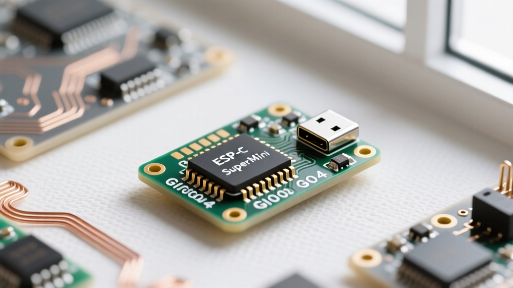
The ESP32-C3 SuperMini has rapidly become the go-to development board for IoT enthusiasts and DIYers replacing their aging ESP8266 modules. Measuring roughly 22x18mm and typically costing between $2.00 and $3.50, this tiny powerhouse features a single-core 32-bit RISC-V processor running at 160MHz, 400KB of SRAM, and native Wi-Fi 4 alongside Bluetooth 5 (LE) support.
However, its ultra-compact footprint comes with specific hardware quirks that can trap beginners. Understanding the ESP32-C3 SuperMini pinout is not just about knowing which pin does what; it is about navigating strapping pins, native USB routing, and onboard LED conflicts. This guide will break down every critical aspect of wiring this board safely and effectively.
The Complete ESP32-C3 SuperMini Pinout Breakdown
Unlike larger development boards, the SuperMini exposes 15 accessible GPIO pins via its dual-row castellated headers. Below is the definitive mapping of the board's physical pins to their internal ESP32-C3 functions.
| Board Pin Label | GPIO Number | Primary Functions | Beginner Gotchas & Notes |
|---|---|---|---|
| 5V | VBUS | USB 5V Power Input/Output | Do NOT feed 5V into the 3V3 pin. Use this to power 5V peripherals. |
| GND | GND | Common Ground | Multiple GND pins are internally connected. |
| 3V3 | VDD | 3.3V Regulated Output | Output of the onboard LDO. Max continuous draw ~200mA. |
| TX / 21 | GPIO21 | UART0 TX, I2C SDA | Defaults to Serial TX. Safe for general I/O. |
| RX / 20 | GPIO20 | UART0 RX, I2C SCL | Defaults to Serial RX. Safe for general I/O. |
| 19 | GPIO19 | USB D+, SPI MISO | Warning: Tied directly to USB-C D+. Using as GPIO disables USB comms. |
| 18 | GPIO18 | USB D-, SPI CLK | Warning: Tied directly to USB-C D-. Using as GPIO disables USB comms. |
| 10 | GPIO10 | SPI CS, I2S, PWM | Excellent pin for general purpose output or SPI Chip Select. |
| 9 | GPIO9 | Boot Button, SPI HD | Tied to the onboard 'BOOT' switch. Pulled HIGH internally. |
| 8 | GPIO8 | Onboard RGB LED (WS2812) | Strapping Pin! Pulling high during boot forces USB-Serial boot mode. |
| 7 | GPIO7 | I2S, PWM, SPI WP | Safe for general I/O and PWM motor control. |
| 6 | GPIO6 | I2S, PWM, SPI MISO | Safe for general I/O. |
| 5 | GPIO5 | ADC1_CH0, I2S, PWM | 12-bit ADC. Note: C3 ADCs are known for slight non-linearity. |
| 4 | GPIO4 | ADC1_CH1, I2S, PWM | 12-bit ADC. Good for basic analog sensor reading. |
| 3 | GPIO3 | Reset / EN | Tied to the onboard 'RST' button. Pull LOW to reset the MCU. |
| 2 | GPIO2 | ADC1_CH2, SPI MOSI | Strapping Pin! Must be LOW to boot from SPI flash. |
| 1 | GPIO1 | ADC1_CH3, I2S, PWM | Safe for general I/O. |
| 0 | GPIO0 | ADC1_CH4, I2S, PWM | Safe for general I/O. |
Critical Wiring Gotchas for Beginners
When transitioning from Arduino Uno or standard ESP32 boards, the SuperMini's dense design introduces a few hardware traps. According to the Espressif ESP-IDF ESP32-C3 Documentation, ignoring these can lead to boot failures or damaged silicon.
1. The Native USB-C Direct Connection Quirk
The ESP32-C3 features an internal USB-Serial/JTAG controller. On the SuperMini, the USB-C data lines are wired directly to GPIO18 (D-) and GPIO19 (D+) without a dedicated USB-to-UART bridge chip like the CP2102 or CH340.
Beginner Rule: Never use GPIO18 and GPIO19 for standard sensors, relays, or I2C devices unless you are absolutely sure you will not need USB serial debugging or OTA flashing via USB. If you wire a relay to GPIO19, toggling it will corrupt your USB data stream and crash your serial monitor.
2. The GPIO8 RGB LED and Strapping Pin Conflict
The hallmark of the genuine SuperMini is the WS2812B RGB LED connected to GPIO8. However, GPIO8 is a critical strapping pin. During the power-on reset phase, the ESP32-C3 samples the logic level of GPIO8 to determine its boot source.
- GPIO8 LOW: Boots normally from the onboard SPI Flash.
- GPIO8 HIGH: Boots into the USB-Serial/JTAG download mode.
Because the WS2812B LED is attached, its internal parasitic capacitance and data line can sometimes cause the pin to float or read HIGH during the exact millisecond the chip samples it, resulting in a "failed to boot" error. If you experience random boot failures, add a 10kΩ pulldown resistor between GPIO8 and GND on your breadboard, or initialize the LED immediately in your setup() function to force the pin LOW.
3. ADC Limitations and Sensor Wiring
Unlike the original dual-core ESP32, the C3 only has one ADC block (ADC1) with 6 channels (GPIO0 to GPIO5). Furthermore, the 12-bit ADC on the RISC-V C3 chip is notoriously noisy at the extreme high and low voltage rails. If you are wiring an analog sensor (like an LDR or potentiometer), avoid using the 0-100mV and 2400-2500mV ranges for precision measurements. Use software oversampling (averaging 16 to 32 reads) to stabilize your data.
Powering the SuperMini: 5V vs 3.3V Rails
A common beginner mistake is misinterpreting the power pins on the castellated headers. The SuperMini utilizes a tiny SOT-23-5 LDO (usually an ME6211C33) to step down USB power.
- The 5V Pin (VBUS): This is directly connected to the USB-C 5V line. You can use this to power 5V peripherals like WS2812 LED strips or HC-SR04 ultrasonic sensors. You can also feed a regulated 5V into this pin to bypass the USB-C port entirely.
- The 3V3 Pin (VDD): This is the output of the onboard LDO. It provides a stable 3.3V. Never feed 5V into the 3V3 pin. Doing so will instantly fry the ESP32-C3 silicon, as the chip's maximum absolute rating on VDD is 3.6V.
- Current Limits: While the LDO datasheet may claim 500mA, the SuperMini's PCB lacks adequate copper pours for heat dissipation. Limit your 3.3V rail draw to 200mA - 250mA continuous to prevent thermal throttling and voltage sag.
Flashing and Boot Mode Troubleshooting
Because the SuperMini lacks an auto-reset circuit for the bootloader (which standard NodeMCU boards use via the DTR/RTS serial lines), you must manually enter download mode when flashing new firmware via the Arduino IDE or PlatformIO.
The Manual Boot Sequence
- Connect the board to your PC via a data-capable USB-C cable (many cheap cables are charge-only and lack the D+/D- wires).
- Press and hold the onboard BOOT button (GPIO9).
- While holding BOOT, press and release the RST button (GPIO3).
- Release the BOOT button.
- Click "Upload" in your IDE. The serial monitor should now show the Espressif bootloader handshake.
Pro-Tip: If your IDE hangs at "Connecting...", your USB cable is likely missing data lines, or your OS lacks the CDC-ACM drivers required for the C3's native USB implementation.
Real-World Project Wiring Example: I2C OLED + BME280
To solidify your understanding of the ESP32-C3 SuperMini pinout, let us map out a common environmental monitoring setup using an SSD1306 OLED and a BME280 sensor.
| Component Pin | SuperMini Pin | Reasoning |
|---|---|---|
| OLED VCC / BME VCC | 3V3 | Both modules support 3.3V logic and power. |
| OLED GND / BME GND | GND | Common ground reference. |
| OLED SDA / BME SDA | GPIO6 | Using GPIO6 avoids the default UART/I2C pins (20/21) keeping serial free. |
| OLED SCL / BME SCL | GPIO7 | Adjacent to GPIO6 for clean breadboard routing. |
By mapping I2C to GPIO6 and GPIO7, we keep GPIO20 and GPIO21 free for UART debugging, and we avoid the USB-tied pins (18/19). In your Arduino code, you would initialize the Wire library using Wire.begin(6, 7);.
Summary
The ESP32-C3 SuperMini is a phenomenal, cost-effective platform for modern IoT projects, provided you respect its hardware boundaries. By memorizing the native USB pin conflicts, respecting the GPIO8 strapping pin behavior, and managing your 3.3V power budget, you can bypass the common pitfalls that frustrate beginners. For deeper technical specifications, always refer to the Official ESP32-C3 Datasheet (PDF) to verify electrical tolerances before wiring high-current peripherals.