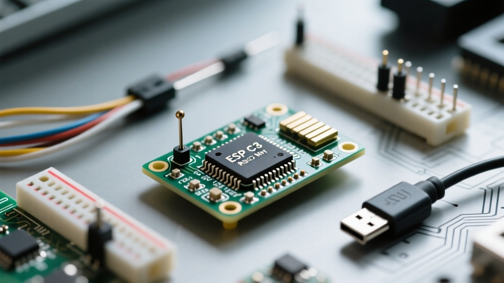

The transition from bulky, dual-core ESP32 development boards to ultra-compact, single-core RISC-V alternatives has fundamentally shifted how electrical engineers and makers approach IoT prototyping. The ESP32 C3 mini ecosystem—encompassing the generic "SuperMini", the Seeed Studio XIAO, and the Wemos Lolin C3 Mini—offers a compelling blend of Wi-Fi connectivity, Bluetooth 5 (LE), and a footprint small enough to embed directly into custom PCBs. However, optimizing your workflow for these boards requires unlearning a few habits from the original Xtensa-based ESP32 era. This guide details the exact IDE configurations, hardware quirks, and power-management strategies required to streamline your ESP32 C3 mini development pipeline.
Hardware Matrix: Selecting the Right C3 Mini Variant
Before writing a single line of C++, your workflow efficiency depends on selecting the correct hardware variant for your deployment phase. While they all share the same 160MHz RISC-V core and 4MB of SPI flash, their peripheral implementations drastically alter your prototyping speed.
| Board Variant | Avg. Price | Battery Management | Best Workflow Use-Case |
|---|---|---|---|
| Generic SuperMini | $3.50 | None (Raw 5V/VBAT pins) | Breadboarding, custom PCB integration |
| Seeed XIAO ESP32C3 | $5.50 | Onboard LiPo Charging IC (JST SH) | Rapid wearable/sensor node deployment |
| Wemos Lolin C3 Mini | $4.00 | None (Standard spacing) | Standard perf-board and shield stacking |
Choosing the XIAO variant eliminates the need for external TP4056 charging modules during the testing phase, saving at least 45 minutes of wiring and debugging per node. Conversely, if you are designing a custom PCB and plan to solder the module directly via castellated pads, the XIAO or specific SuperMini variants with exposed edge pads are mandatory.
Eliminating the "Boot Button Dance" in Your Flashing Workflow
The most notorious workflow bottleneck with the ESP32 C3 mini is the auto-reset circuit—or lack thereof on cheaper clones. On standard DevKits, the DTR/RTS UART lines automatically toggle the EN and GPIO0 (or GPIO9 on C3) pins to enter the serial bootloader. On many generic SuperMini boards, the USB-to-UART bridge (often a CH340 or CP2102) lacks the physical routing to trigger this reset sequence.
The USB-CDC Solution
To bypass holding the "BOOT" button (GPIO9) every time you compile, you must configure the Arduino IDE or PlatformIO to use the native USB CDC (Communication Device Class). In the Arduino IDE Tools menu, apply the following settings:
- USB CDC On Boot: Enabled
- Flash Mode: QIO
- Upload Mode: UART0 / Hardware CDC
By enabling the native USB CDC, the ESP32-C3's internal USB peripheral handles both serial logging and flashing, completely bypassing the external UART bridge's reset limitations. If you are using PlatformIO for VS Code, add build_flags = -DARDUINO_USB_CDC_ON_BOOT=1 to your platformio.ini file to enforce this behavior across your team's workflow and eliminate manual IDE configuration errors.
Architecting for Single-Core Constraints
Unlike the classic ESP32's dual-core Xtensa LX6 architecture, the ESP32-C3 relies on a single-core 32-bit RISC-V processor. This fundamentally changes how you handle FreeRTOS task scheduling and interrupt service routines (ISRs).
Task Prioritization and the Watchdog
In a dual-core setup, you could pin the Wi-Fi stack to Core 0 and your application logic to Core 1. On the ESP32 C3 mini, all tasks share the same execution thread. If your main loop blocks for more than a few milliseconds—perhaps waiting for a slow I2C sensor read or a blocking HTTP POST request—the Wi-Fi stack starves, leading to disconnects or Task Watchdog Timer (TWDT) resets.
To optimize your workflow, adopt a strictly non-blocking, event-driven architecture. Use the xTaskCreate function to offload heavy sensor polling to background tasks with lower priorities than the arduino_events task. Furthermore, always wrap external sensor libraries in timeout handlers to prevent I2C bus lockups from crashing the single core.
Power Profiling: Deep Sleep Without a ULP Coprocessor
A critical piece of information often missing from basic tutorials is that the ESP32-C3 does not feature the Ultra-Low Power (ULP) coprocessor found on the original ESP32 or the ESP32-S3. You cannot wake the board using the ULP while the main cores are powered down.
RTC Memory and Timer Wakeups
To achieve the ~5µA deep sleep current necessary for multi-year CR2032 coin cell deployments, you must rely on the RTC (Real-Time Clock) timer and RTC memory. According to the Espressif ESP32-C3 Technical Reference Manual, the RTC fast memory can retain up to 8KB of data during deep sleep.
Before calling esp_deep_sleep_start(), ensure you explicitly power down the RF and sensor peripherals. A common failure mode in C3 mini workflows is leaving the I2C pull-up resistors energized via the GPIO matrix, which can add 200µA to your sleep current. Always reconfigure your I2C pins to high-impedance inputs (INPUT) or disable them entirely before entering sleep.
#include <esp_sleep.h>

// Retained in RTC memory across deep sleep cycles
RTC_DATA_ATTR int bootCount = 0;

void setup() {
  bootCount++;
  // Power down RTC peripherals to minimize leakage current
  esp_sleep_pd_config(ESP_PD_DOMAIN_RTC_PERIPH, ESP_PD_OPTION_OFF);

  // Sleep for 60 seconds (60,000,000 microseconds)
  esp_deep_sleep(60000000);
}

void loop() {
  // Execution never reaches here
}
Navigating GPIO Constraints and Strapping Pins
The ESP32-C3 features 22 programmable GPIOs, but the "mini" form factors break out significantly fewer. The generic SuperMini typically exposes only 11 usable pins. More importantly, workflow errors frequently occur when developers misuse strapping pins.
GPIO2, GPIO8, and GPIO9 dictate the boot mode and log output. If you wire a sensor that pulls GPIO9 low on startup, the ESP32 C3 mini will perpetually enter the serial bootloader instead of executing your sketch. Always consult the schematic of your specific mini variant and reserve GPIO8 and GPIO9 strictly for internal boot configurations, using them for output-only signals if absolutely necessary.
Streamlining the Deployment Pipeline
For production or field-deployed nodes, over-the-air (OTA) updates are mandatory. The 4MB flash on the ESP32 C3 mini requires careful partition management. Allocate a minimal spiffs partition and maximize the app0 and app1 OTA partitions. By integrating the Arduino ESP32 Core OTA libraries and pairing them with a lightweight MQTT broker, you can push compiled .bin files directly to your C3 mini nodes without ever touching the USB-C cable again. Mastering these constraints turns the ESP32-C3 from a frustrating, quirky board into the most efficient, cost-effective IoT node in your arsenal.