
The entire discipline of electrical engineering relies on a fundamental binary: the controlled movement of electrons through electrical conductors, and the absolute restriction of that movement via insulators. Whether you are sizing a 500 kcmil feeder for a commercial switchboard or selecting PTFE-coated wire for an aerospace avionics bay, understanding the atomic and macroscopic properties of these materials is non-negotiable.
This reference guide moves beyond basic textbook definitions. We will explore the material science, real-world failure modes, and precise selection matrices required for professional electrical design, backed by empirical data and industry standards.
The Atomic Divide: Valence Electrons and Charge Flow
The distinction between a conductor and an insulator is dictated by quantum mechanics—specifically, the band gap between the valence band (where electrons are bound to atoms) and the conduction band (where electrons are free to move).
- Conductors: Metals like copper and silver have overlapping valence and conduction bands. Their outermost electrons are loosely bound, forming a 'sea of electrons' that drift freely under an applied electromotive force (voltage).
- Insulators: Materials like PTFE (Teflon) and cross-linked polyethylene (XLPE) possess a massive band gap (often >5 eV). It requires an extraordinary amount of energy to rip an electron from its atomic orbit and force it into the conduction band.
According to Georgia State University's HyperPhysics, resistivity is the intrinsic property that quantifies this behavior, measured in nano-ohm meters (nΩ·m) for conductors and mega-ohm meters (MΩ·m) for insulators.
Comprehensive Material Reference Chart
The following table contrasts standard electrical conductors and insulators used in modern wiring, component manufacturing, and high-voltage transmission. Data reflects standard conditions (20°C) unless otherwise noted.
| Material | Classification | Conductivity (MS/m) | Resistivity (nΩ·m) | Dielectric Strength (kV/mm) | Max Continuous Temp |
|---|---|---|---|---|---|
| Silver (Pure) | Conductor | 63.0 | 15.9 | N/A | 961°C (Melting) |
| Copper (Annealed) | Conductor | 58.0 | 17.2 | N/A | 1085°C (Melting) |
| Gold (Pure) | Conductor | 45.2 | 24.4 | N/A | 1064°C (Melting) |
| Aluminum (6101-T6) | Conductor | 32.0 | 31.2 | N/A | 660°C (Melting) |
| PTFE (Teflon) | Insulator | ~10⁻¹⁰ | ~10¹⁶ | 60 - 100 | 260°C |
| XLPE | Insulator | ~10⁻¹² | ~10¹⁵ | 25 - 40 | 90°C (250°C Short) |
| PVC (Plasticized) | Insulator | ~10⁻⁸ | ~10¹³ | 15 - 40 | 60°C - 105°C |
| Ceramic (Alumina) | Insulator | ~10⁻¹⁴ | ~10¹⁸ | 10 - 35 | >1000°C |
Real-World Conductor Selection: Beyond Pure Conductivity
While silver is the most conductive element, it is rarely used for bulk wiring due to cost and its tendency to tarnish (forming silver sulfide). Professional wire sizing requires balancing conductivity, mechanical strength, weight, and termination chemistry.
Copper vs. Aluminum: The Weight-to-Cost Matrix
According to the Copper Development Association (CDA), annealed copper is the global baseline for conductivity, defined as 100% IACS (International Annealed Copper Standard). Aluminum, specifically the AA-8000 series alloys mandated by the NEC for branch circuits, operates at roughly 61% of copper's conductivity by volume.
However, aluminum is 70% lighter than copper. In high-voltage overhead transmission lines, the weight savings drastically reduce the structural load on steel towers, making aluminum (often reinforced with a steel core, ACSR) the undisputed standard. In residential and commercial buildings, aluminum requires a larger cross-sectional area (e.g., 2 AWG Aluminum to replace 3 AWG Copper) and mandates the use of anti-oxidant compounds and specific CO/ALR or AL-rated lugs to prevent galvanic corrosion and thermal creep at termination points.
The Danger of Copper-Clad Aluminum (CCA)
CCA wire features an aluminum core with a thin copper wash. While it passes basic visual inspections, it possesses the high DC resistance of aluminum and the termination incompatibility of copper. CCA is highly prone to electromigration and oxidation at receptacle screws, leading to high-resistance connections, localized heating, and arc faults. The NEC strictly prohibits CCA for standard branch circuit wiring.
Insulator Failure Modes and Dielectric Breakdown
Insulators do not fail by 'wearing out' in the traditional mechanical sense; they fail via chemical degradation, thermal runaway, or electrical puncture. Understanding these failure modes is critical when selecting wire insulation for harsh environments.
1. Dielectric Breakdown and Puncture
Every insulator has a dielectric strength, measured in kilovolts per millimeter (kV/mm). If the applied electric field exceeds this threshold, the insulator's atomic bonds are violently ripped apart, creating a conductive plasma channel. For example, standard PVC insulation on a 600V THHN wire is roughly 0.76mm thick. With a dielectric strength of ~20 kV/mm, the insulation can theoretically withstand 15,200 volts before puncturing. However, safety factors and transient voltage spikes dictate the 600V RMS rating.
2. Electrical Tracking and Carbonization
Tracking occurs when micro-arcing on the surface of an insulator (often exacerbated by moisture and dust) degrades the polymer chain. In hydrocarbon-based insulators like PVC or PE, this arcing strips away hydrogen, leaving behind microscopic paths of pure carbon. Because carbon is a conductor, these 'tracks' eventually bridge the gap between conductors, resulting in a catastrophic short circuit. Materials like PTFE and ceramics are highly track-resistant.
3. Thermal Degradation and Polymer Chain Scission
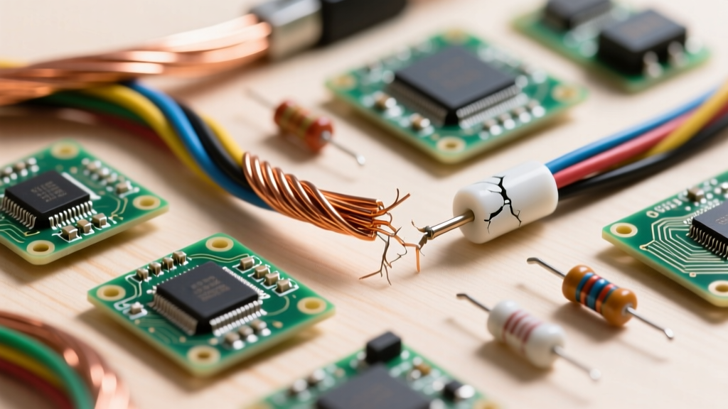
When insulation exceeds its thermal rating, the plasticizers in PVC begin to volatilize and evaporate. The wire becomes brittle, and microscopic cracks form. Once the physical barrier is compromised, moisture ingress leads to ground faults. This is why high-temperature environments (like industrial ovens or engine bays) require silicone rubber, fiberglass braiding, or PTFE.
Wire Insulation Coding and Application Guide
The National Electrical Code (NEC) utilizes a specific lettering system to denote the chemical makeup and environmental limits of electrical insulators. Referencing the Anixter Wire & Cable Handbook, here is a breakdown of the most common insulation chemistries:
- THHN / THWN-2 (PVC with Nylon Jacket): The standard for commercial conduit. The PVC provides dielectric insulation, while the thin polyamide (nylon) outer jacket provides exceptional abrasion resistance and moisture protection. Rated 90°C in dry locations, 75°C in wet.
- XHHW-2 (Cross-Linked Polyethylene): XLPE is created by irradiating or chemically treating polyethylene to form 3D molecular bonds. This drastically improves thermal stability and moisture resistance. XHHW-2 is rated 90°C in both wet and dry locations and has a smaller outer diameter than THHN, allowing for more conductors in a single conduit.
- PTFE / FEP (Fluoropolymers): Used in aerospace, military (MIL-W-22759), and high-end audio. PTFE is virtually inert, impervious to most chemicals, and can withstand continuous temperatures up to 260°C. It also exhibits an exceptionally low dielectric constant, making it the premier insulator for high-frequency RF and data transmission where signal capacitance must be minimized.
- CMP (Plenum-Rated): Standard PVC releases highly toxic hydrochloric acid (HCl) gas and thick black smoke when burned. Wires routed in HVAC plenum spaces must use FEP or specialized low-smoke, zero-halogen (LSZH) compounds to prevent toxic gas circulation during a fire.
Expert Derating Note: Insulation temperature ratings (e.g., 90°C for THHN) are used for ampacity derating calculations when bundling multiple current-carrying conductors in a raceway. However, the final allowable ampacity is almost always limited by the 75°C rating of the termination lugs on standard breakers and receptacles, per NEC 110.14(C).
Summary Decision Framework
When engineering a circuit or selecting wire for a custom harness, apply this sequential framework:
- Determine Current & Voltage: Calculate the baseline AWG size based on ampacity and acceptable voltage drop (typically <3% for branch circuits).
- Assess the Thermal Environment: If ambient temperatures exceed 30°C, or if the wire will be bundled tightly, select XLPE or PTFE over standard PVC to leverage higher thermal headroom.
- Evaluate Mechanical & Chemical Stress: Choose Nylon-jacketed THHN for conduit pulling abrasion, or Silicone/Fiberglass for continuous flexing and high-heat machinery.
- Verify Termination Compatibility: Ensure the chosen conductor alloy (Copper vs. Aluminum) and insulation thickness do not compromise the physical connection at the lug or terminal block.
Mastering the interplay between electrical conductors and insulators is what separates a basic DIY wiring job from a robust, code-compliant, and failure-proof electrical installation.