
Phase 1: Deconstructing the Waterproof DS18B20 Architecture
Transitioning from basic breadboard electronics to real-world environmental monitoring requires robust components. The waterproof ds18b20 water temperature sensor is the gold standard for liquid thermal measurement in DIY and industrial IoT projects. Originally designed by Dallas Semiconductor (later Maxim Integrated, and now Analog Devices), the DS18B20 communicates via the 1-Wire protocol, requiring only a single digital pin for bidirectional data transfer.
The waterproof variant encapsulates the standard TO-92 silicon chip inside a 304 stainless steel tube, sealed with industrial epoxy. This specific packaging allows for direct submersion in water, hydroponic nutrient solutions, and soil matrices. However, understanding the internal architecture is critical for skill-building. Every single sensor contains a unique, factory-lasered 64-bit ROM. This includes a 48-bit serial number, an 8-bit CRC (Cyclic Redundancy Check) for data validation, and an 8-bit family code (0x28). This unique identifier means you can daisy-chain dozens of sensors on a single microcontroller GPIO pin, a massive advantage over analog thermistors that require individual ADC pins and complex voltage-divider calibration.
Phase 2: Hardware Wiring and the 4.7kΩ Pull-Up Rule
The most common point of failure for beginners is ignoring the electrical realities of the 1-Wire bus. The DS18B20 utilizes an open-drain architecture for its data line. This means the sensor can pull the bus LOW (to ground), but it cannot drive the bus HIGH. Therefore, a hardware pull-up resistor is absolutely mandatory to return the line to VDD when the sensor is not actively transmitting.
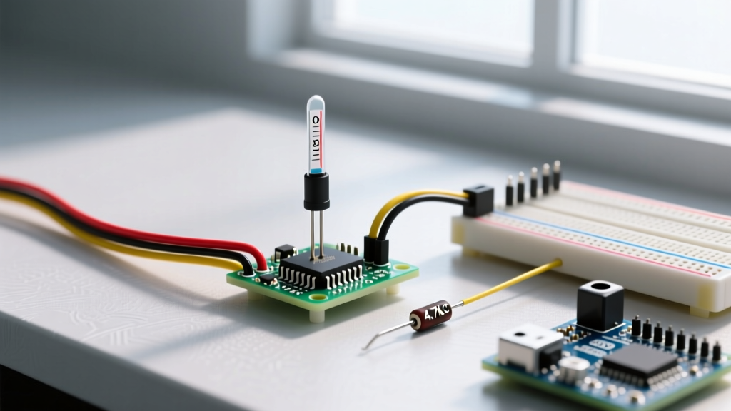
For standard cable runs under 5 meters, a 4.7kΩ resistor connected between the Data line and the 3.3V or 5V VDD line is required. If you omit this resistor, your microcontroller will read floating noise, resulting in erratic data or complete bus failure.
Waterproof Probe Pinout and Power Modes
The waterproof ds18b20 water temperature sensor typically features a 3-wire PVC or silicone jacket. Wiring it incorrectly will not damage the chip immediately due to internal protection diodes, but it will yield no data.
| Wire Color | Function | External Power Mode | Parasitic Power Mode |
|---|---|---|---|
| Red | VDD (Power) | Connect to 3.3V or 5V | Connect to GND |
| Black | GND (Ground) | Connect to GND | Connect to GND |
| Yellow/White | Data (DQ) | Connect to GPIO + 4.7kΩ Pull-Up | Connect to GPIO + 4.7kΩ Pull-Up |
Note: While Parasitic Power mode (drawing power directly from the data line) is supported by the silicon, it is highly discouraged for waterproof probes. The voltage drop over long, unshielded cables often leads to brownouts during the active temperature conversion phase, causing silent data corruption.
Phase 3: Firmware Integration and Resolution Timing
When writing firmware for Arduino, ESP32, or Raspberry Pi Pico environments, the PJRC OneWire library combined with the DallasTemperature wrapper is the industry standard. However, a critical skill in embedded systems is managing blocking delays.
The DS18B20 features a configurable internal ADC that supports 9-bit, 10-bit, 11-bit, and 12-bit resolutions. By default, the sensor boots into 12-bit mode, which provides a highly granular 0.0625°C increment. The trade-off is conversion time. A 12-bit conversion requires exactly 750 milliseconds of active processing time inside the sensor.
If you call sensors.requestTemperatures() and immediately attempt to read the bus, you will pull stale data from the sensor's scratchpad RAM. You must implement a non-blocking timer or a strict delay(750) to allow the analog-to-digital conversion to complete. For battery-powered ESP32 nodes, dropping the resolution to 9-bit (0.5°C accuracy) reduces the conversion delay to just 94ms, drastically improving deep-sleep wake cycles and preserving battery life.
Phase 4: Diagnosing the '85°C' and '-127°C' Ghost Readings
As you build more complex environmental arrays, you will inevitably encounter 'ghost' readings. Mastering the ds18b20 water temperature sensor requires knowing how to diagnose these specific failure codes without blindly replacing hardware.
The 85°C Power-On Reset (POR) Anomaly
If your serial monitor suddenly outputs exactly 85.00°C, your sensor has not spontaneously boiled. According to the Analog Devices DS18B20 Datasheet, 85°C is the factory default value stored in the scratchpad register upon initial power-up. If you read 85°C, it means your microcontroller successfully queried the sensor's ROM, but the temperature conversion command was either never sent, interrupted, or failed due to a voltage brownout before the new value could be written to the scratchpad.
The -127°C Bus Disconnect
A reading of -127°C (or sometimes -196°C depending on the library wrapper) indicates a complete failure of the 1-Wire bus. The microcontroller is failing to detect the sensor's 64-bit ROM presence pulse. This is almost always caused by a missing 4.7kΩ pull-up resistor, a severed data wire inside the waterproof epoxy seal, or severe galvanic corrosion on the TO-92 legs due to water ingress.
Phase 5: Pushing Limits: Long Cable Runs and Capacitance
The 1-Wire protocol is highly susceptible to parasitic capacitance. When you deploy a ds18b20 water temperature sensor in a large agricultural tank or a multi-story hydroponic setup, cable length becomes your primary adversary. Standard unshielded CAT5 or PVC sensor cables introduce roughly 50pF of capacitance per meter.
Once your cable run exceeds 10 to 15 meters, the 4.7kΩ pull-up resistor forms an RC (Resistor-Capacitor) low-pass filter with the cable's parasitic capacitance. The voltage rise time on the data line becomes too slow, and the microcontroller misinterprets the sluggish edges as bit errors, resulting in CRC (Cyclic Redundancy Check) validation failures.
The Engineering Fix: To combat long-run capacitance, you must lower the pull-up resistance to provide a stronger current source, pulling the line HIGH faster. For runs between 10 and 20 meters, drop the pull-up resistor to 2.2kΩ. For extreme runs up to 50 meters, use a 1kΩ resistor and ensure you are using External Power mode to maintain signal integrity. Always implement CRC checking in your software loop; if the OneWire library returns a CRC mismatch, discard the payload and retry rather than logging corrupted thermal data.
Authoritative References and Further Reading
- Analog Devices DS18B20 Official Datasheet - Essential reading for scratchpad memory maps and timing diagrams.
- PJRC OneWire Library Documentation - The foundational C++ implementation for Arduino and Teensy ecosystems.
- Adafruit Waterproof DS18B20 Guide - Excellent visual references for breadboard wiring and pull-up placement.