
Introduction: Mastering the Workbench Essential
Whether you are debugging a custom Arduino circuit, troubleshooting a dead automotive battery, or verifying residential wiring, the digital multimeter (DMM) is your primary diagnostic tool. Yet, many beginners and even seasoned DIYers struggle with the core question: how do you use a multimeter safely and accurately? Misunderstanding the fundamental difference between measuring voltage in parallel versus current in series can lead to blown fuses, destroyed components, or severe electrical shock.
In this comprehensive fundamentals explainer, we will bypass the superficial fluff and dive deep into the exact methodologies, safety categories, and real-world failure modes associated with digital multimeters. By the end of this guide, you will understand not just which buttons to press, but the electrical theory dictating why those measurements work.
The Anatomy of a Digital Multimeter (DMM)
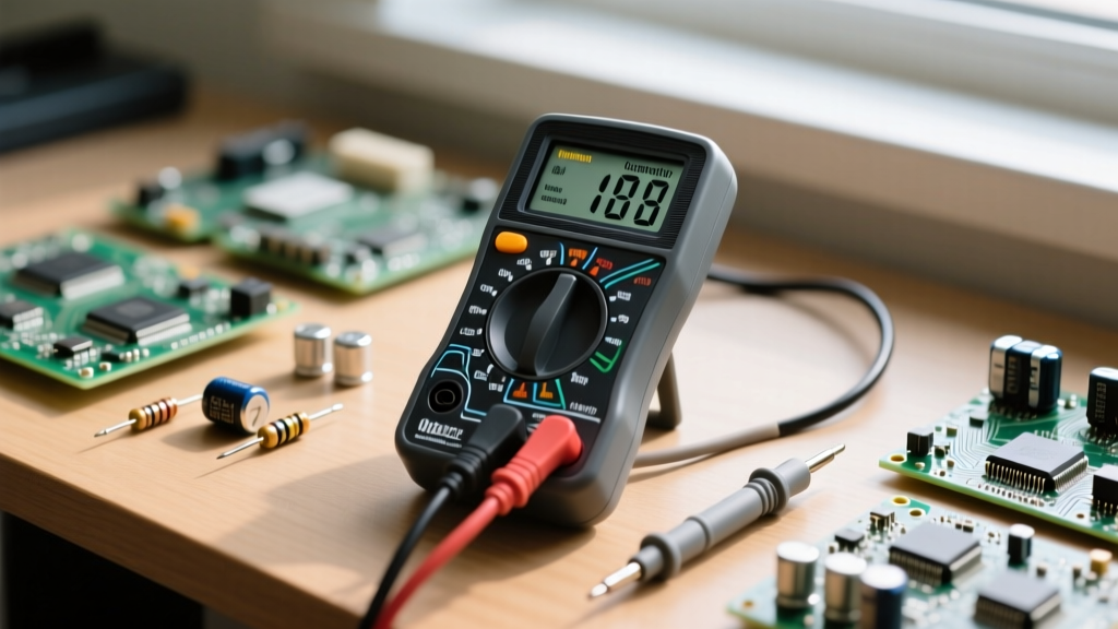
Before taking a single measurement, you must understand the physical interface of your device. While models range from the budget-friendly AstroAI DM1100 (around $15) to the industry-standard Fluke 117 (approximately $200), the core anatomy remains consistent.
- The Display: Shows the numerical readout. Advanced models feature analog bar graphs to visualize rapid fluctuations.
- The Selection Dial: Allows you to choose the measurement type (Voltage, Current, Resistance) and the expected range.
- The Input Jacks (Ports): This is where most catastrophic beginner errors occur. You will typically find three or four ports:
- COM (Common): The black probe always connects here. It serves as the ground or reference point for your measurements.
- VΩmA: The red probe connects here for measuring Voltage (V), Resistance (Ω), and low-level current (usually fused at 200mA or 400mA).
- 10A (or 20A): A separate, often unfused or high-fused port for measuring high current.
Expert Insight: The most common way beginners destroy their multimeters is by leaving the red probe in the 10A current port and then attempting to measure voltage across a power supply. Because the current port has near-zero internal resistance (a shunt), connecting it in parallel across a voltage source creates a dead short, resulting in a violent arc and a blown internal HRC (High Rupturing Capacity) fuse.
Step-by-Step: Core Measurements Explained
To truly understand how do you use a multimeter in practical scenarios, we must break down the three primary measurement modes. For deeper visual references on probe placement, SparkFun's Multimeter Tutorial remains one of the most reliable visual guides on the internet.
1. Measuring Voltage (Parallel Connection)
Voltage is the electrical potential difference between two points. Because you are measuring the difference across a component or source, voltage must always be measured in parallel.
- DC Voltage (V⎓ or VDC): Used for batteries, USB power, and microcontroller logic levels. To test a standard AA battery, set the dial to the 20V DC range. Place the red probe on the positive terminal and the black on the negative. A fresh alkaline cell will read between 1.55V and 1.60V. If it reads below 1.20V, it is effectively dead for high-drain applications.
- AC Voltage (V~ or VAC): Used for wall outlets and mains power. Warning: Only measure AC mains if your multimeter is rated CAT III or higher and you are using properly insulated probes. In North America, a standard wall outlet will read between 115V and 125V AC.
2. Testing Continuity and Resistance (Dead Circuits Only)
Resistance (measured in Ohms, Ω) is the opposition to current flow. Continuity is a binary pass/fail test for resistance, usually indicated by an audible beep.
The Golden Rule: You must never measure resistance or continuity on a live, powered circuit. The multimeter outputs a small known voltage from its internal battery to calculate resistance. If external voltage is present, it will backfeed into the multimeter's analog-to-digital converter (ADC), potentially frying the IC.
- Disconnect all power from the circuit.
- Set the dial to the Continuity mode (represented by a sound wave or diode symbol).
- Touch the probes together to verify the internal fuse is intact (you should hear a beep).
- Place probes across a trace, wire, or fuse. A beep indicates a continuous path (typically under 30Ω). An 'OL' (Over Limit) reading indicates a broken connection or blown fuse.
3. Measuring Current (Series Connection - The Danger Zone)
Current (Amperes) is the actual flow of electrons through a conductor. To measure flow, the multimeter must become part of the path. Therefore, current must always be measured in series. This means you must physically break the circuit and route the current through the multimeter.
Real-World Scenario: You want to measure the current draw of a 12V DC cooling fan.
- Disconnect the fan's ground wire from the power supply.
- Set your multimeter to the 10A port and dial to DC Amps.
- Connect the red probe to the disconnected ground wire, and the black probe to the power supply's ground terminal.
- Power on the supply. The current now flows from the supply, through the fan, into the red probe, through the multimeter's internal shunt resistor, and out the black probe back to the supply.
Note on Burden Voltage: All multimeters introduce a small voltage drop (burden voltage) when measuring current due to the internal shunt resistor. In highly sensitive, low-voltage microcontroller circuits, this drop can cause the target device to brownout and reset. In these cases, use a dedicated current shunt and measure the millivolt drop across it instead.
Decoding Safety: CAT Ratings and Transients
When learning how do you use a multimeter on household or industrial wiring, the DC voltage rating printed on the probes is not enough. You must understand Measurement Categories (CAT ratings), which define the tool's ability to survive high-energy voltage transients (spikes) common in AC mains environments. The OSHA Electrical Safety guidelines heavily emphasize using properly rated test equipment to prevent arc flash injuries.
| CAT Rating | Environment Description | Transient Risk Level |
|---|---|---|
| CAT II | Local level: Standard wall outlets, plug-in appliances, and portable tools. | Moderate (Dampened by branch circuit impedance) |
| CAT III | Distribution level: Fixed installations, breaker panels, heavy HVAC motors, and lighting systems. | High (Closer to the transformer source) |
| CAT IV | Origin of installation: Service entrances, primary overcurrent protection, and outdoor utility lines. | Extreme (Highest available fault current) |
For a complete breakdown of impulse withstand voltages, refer to the Fluke Corporation's Guide to CAT Ratings, which details how a CAT III 600V meter is vastly superior to a CAT II 1000V meter in surviving transient spikes.
Pro-Tips: Auto-Ranging vs. Manual-Ranging
Modern multimeters come in two primary flavors regarding range selection:
- Manual-Ranging: You must select the expected magnitude (e.g., 2V, 20V, 200V). If you test a 9V battery on the 2V setting, the screen will read 'OL' or '1'. You must step up the range. The advantage is speed; the meter reads instantly without hunting for the correct decimal placement.
- Auto-Ranging: The meter automatically cycles through its internal relays to find the correct scale. While convenient for beginners, auto-ranging can take 2 to 4 seconds to stabilize. When measuring rapidly fluctuating signals or performing continuity sweeps on a large wiring harness, the relay delay can be frustrating.
Summary: Building a Diagnostic Framework
Mastering the multimeter is less about memorizing dial positions and more about understanding the electrical topology of your target circuit. Always ask yourself: Am I measuring potential difference (parallel/voltage) or electron flow (series/current)? Is the circuit live or dead? Is my tool rated for the transient energy of this environment?
By respecting the internal fusing limits, utilizing the correct CAT-rated probes, and understanding the physics behind the readout, you transform the multimeter from a simple number-displayer into a powerful diagnostic extension of your own troubleshooting intuition.