
When building DIY security systems or automated lighting, the HC-SR501 PIR motion sensor is arguably the most ubiquitous component in a beginner's arsenal. Costing barely $2 on the hobbyist market, this module packs a surprising amount of analog signal conditioning into a tiny footprint. However, its simplicity is deceptive. Many beginners encounter "ghost triggers," continuous HIGH states, or fried microcontroller pins because they misunderstand the underlying pyroelectric physics and the specific quirks of the onboard BISS0001 chip. This tutorial goes beyond basic blink sketches, providing a deep-dive into calibration, logic-level safety, and real-world noise mitigation.
The Physics Inside the HC-SR501 PIR Motion Sensor
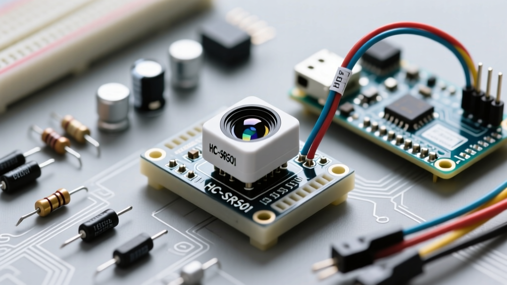
At the heart of the module, hidden beneath the milky-white polyethylene dome, lies a pyroelectric sensor. This dome is not just a protective cover; it is a Fresnel lens that focuses infrared radiation onto the sensor element while expanding the field of view to approximately 120 degrees and a range of up to 7 meters.
The actual sensor element contains two slots made of a crystalline material (usually lithium tantalate) that generates a voltage spike when exposed to heat differentials. When the sensor is idle, both slots detect the same ambient room temperature, resulting in a net-zero output. However, when a warm body walks across the field of view, it intercepts one half of the sensor before the other. This creates a differential voltage spike—first positive, then negative. The module's analog circuitry detects this specific alternating signature, filtering out slow ambient temperature changes (like the sun moving across the room) and only reacting to rapid, localized heat movement.
For a deeper understanding of the optical physics involved, Adafruit's comprehensive PIR guide provides excellent visual breakdowns of how the Fresnel lens creates multiple detection zones.
Module Anatomy: Calibrating the BISS0001 Chip
The raw microvolt signals from the pyroelectric element are useless to a digital microcontroller. The HC-SR501 uses the BISS0001 PIR Controller IC to amplify the signal, run it through two stages of operational amplifiers, and apply a complex window comparator to determine if motion has actually occurred.
As a builder, you interface with this conditioning circuit via two blue trimpots (potentiometers) and a jumper block on the PCB.
The Trimpots: Sensitivity and Time Delay
- Sx (Sensitivity / Distance): Adjusts the gain of the first-stage op-amp. Turning it fully clockwise maximizes the detection range (up to 7m) but makes the sensor highly susceptible to RF interference and minor heat fluctuations. Turning it counter-clockwise reduces the range to roughly 3m, ideal for confined spaces like a pantry or hallway.
- Tx (Time Delay): Dictates how long the OUT pin stays HIGH after motion is no longer detected. At its minimum (fully counter-clockwise), the delay is approximately 0.3 seconds. At its maximum (fully clockwise), the output remains HIGH for roughly 200 seconds (over 3 minutes).
Trigger Mode Selection
Adjacent to the trimpots is a 3-pin header with a jumper cap. This configures the BISS0001's retriggering behavior:
| Jumper Position | Mode Name | Behavior Description | Best Use Case |
|---|---|---|---|
| Outer Pins (H) | Repeat Trigger | Timer resets continuously as long as motion is detected. Output stays HIGH. | Staircase lighting, security alarms. |
| Inner Pins (L) | Single Trigger | Timer runs for the set delay time and ignores all motion until the blocking period ends. | Automated camera traps, timed counters. |
HC-SR501 Pinout and Microcontroller Wiring
The module features a standard 3-pin JST connector: VCC, OUT, and GND. While wiring to a 5V Arduino Uno is straightforward, integrating the HC-SR501 into modern 3.3V ecosystems (like the ESP32 or Raspberry Pi Pico) requires critical attention to voltage tolerances.
The 3.3V Logic Trap
The HC-SR501 requires an operating voltage between 4.5V and 20V. Therefore, you must power the VCC pin with 5V. However, the digital OUT pin outputs the same voltage as VCC. If you power the sensor with 5V, the OUT pin will push 5V into your microcontroller's GPIO pin. If you are using an ESP32, sending 5V into a standard GPIO will degrade or permanently destroy the silicon.
Pro-Tip: When using an ESP32, power the HC-SR501 VCC with 5V, but place a simple voltage divider (e.g., a 1kΩ and 2kΩ resistor pair) between the sensor's OUT pin and the ESP32's GPIO to step the 5V logic down to a safe ~3.3V.
For standard 5V Arduino Uno boards, wire VCC to 5V, GND to GND, and OUT directly to Digital Pin 2. For more on safely reading digital signals, refer to the official Arduino digitalRead documentation.
Writing Robust Arduino Code (Avoiding the Delay Trap)
Beginners often write code that relies on delay(), which halts the microcontroller. Furthermore, they fail to account for the HC-SR501's mandatory initialization period. Upon receiving power, the BISS0001 chip requires roughly 30 to 60 seconds to sample the ambient infrared background and establish a baseline. During this window, the sensor will output erratic HIGH signals or remain completely locked.
// HC-SR501 Robust Reading Sketch
const int pirPin = 2;
const int ledPin = 13;
unsigned long calibrationTime = 30000; // 30 seconds warm-up

void setup() {
  pinMode(pirPin, INPUT);
  pinMode(ledPin, OUTPUT);
  Serial.begin(9600);

  Serial.println("Calibrating sensor... Do not move.");
  for(int i = 0; i < calibrationTime/1000; i++){
    Serial.print(".");
    delay(1000);
  }
  Serial.println("\nSensor Active.");
}

void loop() {
  int motionState = digitalRead(pirPin);

  if (motionState == HIGH) {
    digitalWrite(ledPin, HIGH);
    Serial.println("Motion Detected!");
  } else {
    digitalWrite(ledPin, LOW);
  }
  delay(50); // Small debounce delay
}
Advanced Troubleshooting: Solving Ghost Triggers
The most common complaint on electronics forums regarding the HC-SR501 is "ghost triggering"—the sensor randomly firing HIGH when no human is in the room. This is rarely a defective sensor; it is almost always an environmental or electrical design flaw.
Common Failure Modes and Fixes
- Power Supply Ripple Noise: The BISS0001's internal op-amps are incredibly sensitive to voltage fluctuations. If you power the sensor from a cheap USB wall-wart or a noisy PC USB port, the voltage ripple mimics the pyroelectric spike, causing false triggers. The Fix: Solder a 100µF electrolytic capacitor directly across the VCC and GND pads on the sensor PCB to smooth out the power delivery.
- Thermal Drafts: PIR sensors detect changes in heat. An HVAC vent blowing warm air across a cold room, or even a pet sleeping near a radiator, will trigger the differential slots. The Fix: Relocate the sensor away from HVAC registers, direct sunlight, and exterior drafty doors.
- RF Interference (RFI): The high-impedance analog traces on the HC-SR501 PCB act as tiny antennas. If you place a Wi-Fi router, a 2.4GHz transceiver, or a high-power relay within 12 inches of the sensor, the electromagnetic field will induce a voltage in the sensor traces. The Fix: Maintain physical separation from RF sources, or shield the back of the sensor PCB with grounded copper tape.
By understanding the analog nature of the HC-SR501 PIR motion sensor, you transition from simply copying tutorials to engineering reliable, production-ready IoT environments. Respect the warm-up time, manage your logic levels, and filter your power supply, and this $2 component will perform flawlessly for years.