
The Workhorse of IoT: Understanding the DOIT ESP32 DEVKIT V1
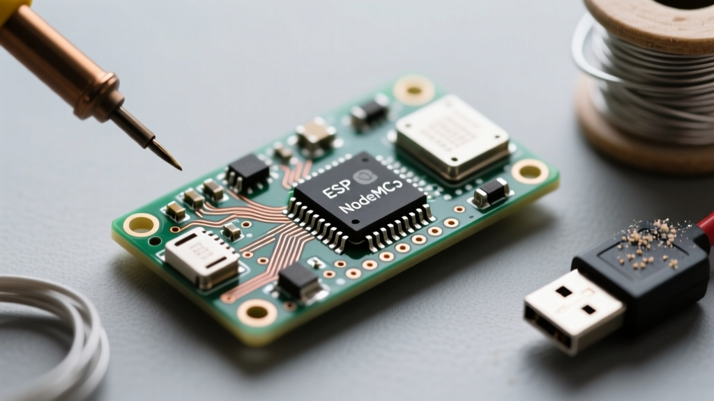
If you have spent any time in the maker community, you have inevitably encountered the DOIT ESP32 DEVKIT V1. Priced typically between $5 and $8 on platforms like AliExpress and Amazon, this development board has become the de facto standard for DIY IoT projects, smart home sensors, and edge-computing prototypes. Built around the Espressif ESP-WROOM-32 module, it packs a dual-core 240MHz Xtensa LX6 processor, 520KB of SRAM, and 4MB of external SPI flash memory into a remarkably accessible form factor.
However, its low cost and massive production volume across various third-party factories mean that makers frequently run into hardware quirks, driver conflicts, and upload failures. This comprehensive tutorial will walk you through the exact hardware anatomy, driver installation, Arduino IDE configuration, and real-world troubleshooting required to successfully flash and deploy code on the DOIT ESP32 DEVKIT V1.
Hardware Anatomy and Breadboard Realities
Before writing a single line of code, it is critical to understand the physical layout of your specific board. The DOIT V1 generally ships in two distinct pinout variations:
- The 30-Pin Version: This is the most breadboard-friendly iteration. When plugged into a standard 830-point solderless breadboard, it leaves one row of tie-points exposed on either side, allowing you to wire components directly.
- The 38-Pin Version: This board breaks out additional GPIOs, including extra ADC and touch pins. However, its wider footprint completely covers the center trench of a standard breadboard, leaving no room for jumper wires on the inner rows. You will need a specialized ESP32 breadboard adapter or two separate breadboards to use this version effectively.
The ADC2 and WiFi Conflict
A common trap for beginners using the DOIT ESP32 DEVKIT V1 is attempting to use analog sensors while WiFi is active. The ESP32's ADC2 (Analog-to-Digital Converter 2) pins share internal hardware resources with the WiFi radio. If your sketch initializes WiFi, any attempt to read from ADC2 pins (such as GPIO 0, 2, 4, 12, 13, 14, 15, 25, 26, and 27) will fail or return garbage data. For analog sensing in IoT projects, always route your sensors to ADC1 pins (GPIO 32, 33, 34, 35, 36, 39).
Identifying Your USB-to-UART Bridge
The DOIT V1 does not use native USB; it relies on an intermediary chip to translate USB data from your computer into UART serial data for the ESP32. Depending on the manufacturing batch, your board will feature one of two chips:
- Silicon Labs CP2102: Usually housed in a square QFN-28 package. This is the premium, more reliable bridge.
- WCH CH340G: Usually a larger rectangular SOIC-16 package. This is the budget alternative found on the cheapest clones.
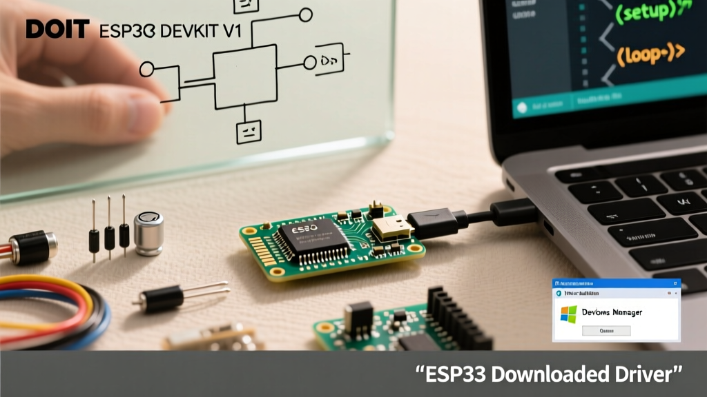
Plug your board into your PC and open your operating system's Device Manager (Windows) or System Information (macOS). If you see a device labeled "CP210x USB to UART Bridge," you need the official Silicon Labs CP210x VCP Drivers. If it shows up as "USB-SERIAL CH340," you must source the CH340 driver instead. Installing the wrong driver is the number one cause of "Port not found" errors in the Arduino IDE.
Step-by-Step Arduino IDE Configuration
With your drivers installed, it is time to configure the Arduino IDE. Espressif maintains an excellent open-source core for the ESP32, which you can integrate directly into the IDE's Board Manager.
Adding the Board Manager URL
Navigate to File > Preferences in the Arduino IDE. In the "Additional boards manager URLs" field, paste the official Espressif JSON link:
https://raw.githubusercontent.com/espressif/arduino-esp32/gh-pages/package_esp32_index.json
For deeper technical references regarding the underlying silicon, you can always consult the official ESP32-WROOM-32 Datasheet.
Selecting the Correct Board Parameters
Open the Boards Manager, search for "esp32", and install the latest stable release by Espressif Systems. Once installed, configure your toolchain with these exact settings for the DOIT V1:
- Board: DOIT ESP32 DEVKIT V1
- Upload Speed: 921600 (This drastically reduces compile-to-flash times compared to the default 115200)
- CPU Frequency: 240MHz (WiFi/BT mode)
- Flash Frequency: 80MHz
- Flash Mode: QIO
- Partition Scheme: Default 4MB with spiffs (Change this only if you need OTA updates or massive local web servers)
Overcoming the "Failed to Connect" Boot Error
Every maker who uses the DOIT ESP32 DEVKIT V1 eventually encounters this infamous error in the Arduino IDE output console:
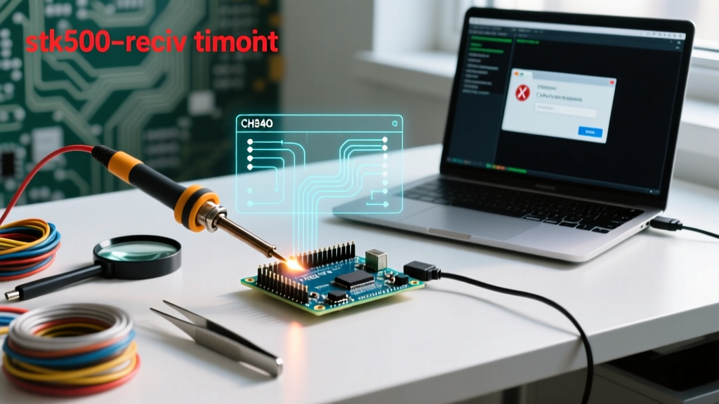
A fatal error occurred: Failed to connect to ESP32: Timed out waiting for packet header
This happens because the ESP32 requires GPIO 0 to be pulled LOW during the exact moment the chip resets to enter the UART bootloader. While the DOIT board has an automatic boot circuit (using transistors to toggle GPIO 0 and EN via the DTR and RTS serial lines), cheap clone boards often have mismatched resistor values or missing capacitors that cause the timing to fail.
The Manual Boot Sequence Workaround
When the IDE output shows "Connecting..." followed by a series of dots, execute this physical sequence on your board:
- Press and hold the BOOT button (this pulls GPIO 0 LOW).
- While holding BOOT, press and release the EN (Enable/Reset) button.
- Release the BOOT button.
The ESP32 will reboot directly into flash mode, and the Arduino IDE will immediately begin uploading your sketch. Once the upload reaches 100%, press the EN button one final time to boot into your newly flashed application.
Power Delivery and Voltage Tolerances
Powering the DOIT ESP32 DEVKIT V1 incorrectly is a fast track to frying the onboard voltage regulator or browning out the chip during WiFi transmission spikes. The ESP32 can draw upward of 350mA in short bursts when transmitting over WiFi. Understanding the board's power rails is essential.
| Power Source | Voltage Input | Max Practical Current | Engineering Notes |
|---|---|---|---|
| Micro-USB Port | 5.0V | ~500mA | Routes through the AMS1117-3.3 LDO. High current draws will cause the LDO to overheat and trigger thermal shutdown. |
| 3V3 Pin | 3.3V | ~800mA | Bypasses the onboard LDO entirely. Ideal for battery-powered setups using an external 3.3V buck converter. |
| VIN Pin | 5.0V to 12V | Varies by Voltage | Feeds the AMS1117-3.3. Do not exceed 9V, or the LDO will dissipate excessive heat (P = (Vin - 3.3) * I). |
If you are designing a custom PCB or wiring a permanent installation, bypass the Micro-USB port and feed a clean 3.3V source directly into the 3V3 pin. This eliminates the thermal bottleneck of the AMS1117 regulator and ensures stable operation during heavy RF transmission.
Your First Flash: The GPIO 2 Blink Test
Unlike some Arduino boards that feature an LED on GPIO 13, the DOIT ESP32 DEVKIT V1 features a tiny blue LED connected directly to GPIO 2. This pin is also tied to the internal boot strapping resistors, but it is perfectly safe to use as an output once the board has successfully booted.
Upload the following sketch to verify your toolchain, driver, and hardware are functioning perfectly:
// DOIT ESP32 DEVKIT V1 Blink Test
#define LED_BUILTIN 2

void setup() {
  pinMode(LED_BUILTIN, OUTPUT);
  Serial.begin(115200);
  Serial.println("DOIT V1 Boot Successful!");
}

void loop() {
  digitalWrite(LED_BUILTIN, HIGH);
  delay(500);
  digitalWrite(LED_BUILTIN, LOW);
  delay(500);
}
If the blue LED pulses and your serial monitor displays the boot message, you have successfully conquered the DOIT ESP32 DEVKIT V1 setup process. You are now ready to leverage its dual-core processing and onboard WiFi/Bluetooth for advanced IoT applications. For further exploration of the ESP32's API and advanced libraries, refer to the official Espressif Arduino Core GitHub repository.