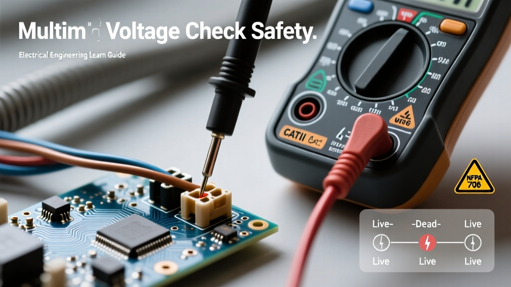

The DIY Electrician's Reality: Why Your Multimeter Matters
When you transition from swapping out light fixtures to diagnosing complex wiring faults, a non-contact voltage tester is no longer enough. You need precision, and that means relying on a multimeter for electrical testing. Whether you are troubleshooting a dead receptacle, mapping out unmarked wires in a junction box, or verifying a DIY subpanel installation, your digital multimeter (DMM) is the ultimate source of truth. However, using a DMM on live mains voltage introduces severe risks if the tool or the technique is flawed.
This guide bypasses the generic 'how to read a dial' tutorials and dives straight into advanced DIY electrical testing scenarios, real-world failure modes, and the specific hardware required to keep you safe while working on 120V/240V residential systems.
Choosing the Right Multimeter for Electrical Testing at Home
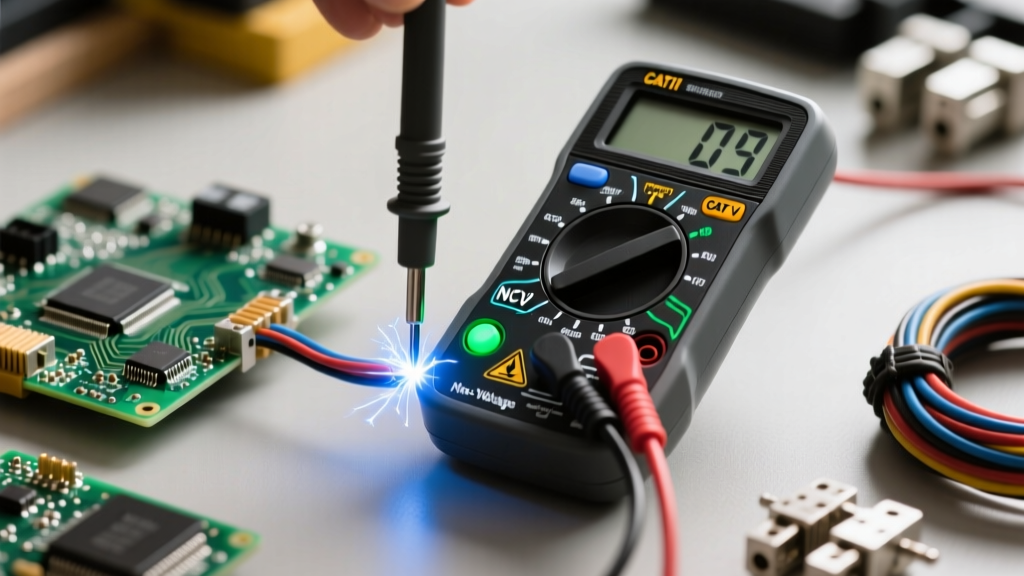
Not all multimeters are created equal. A $15 bargain-bin meter might measure a 9V battery perfectly, but connecting it across a 240V dryer outlet could result in a catastrophic arc flash. For residential DIY electrical testing, you must look at two critical specifications: CAT Ratings and Internal Fusing.
CAT III vs. CAT IV: Decoding the Safety Ratings
The Category (CAT) rating defines the meter's ability to withstand transient voltage spikes (like a nearby lightning strike or utility switching surge). According to Fluke's guide on CAT ratings, the rating isn't just about maximum voltage; it's about the energy capacity of the circuit you are testing.
- CAT III 600V: Required for testing branch circuits, fixed receptacles, and hardwired appliances. This is the minimum acceptable rating for indoor home DIY projects.
- CAT IV 600V: Necessary if you are working at the service entrance, the main breaker panel, or the outdoor meter base where fault currents are exponentially higher.
True RMS and HRC Fuses
Always buy a True RMS meter. Average-responding meters will give wildly inaccurate readings on non-linear loads like LED drivers or variable-speed motor controllers. Furthermore, open the battery compartment before buying. If you see a cheap glass fuse, walk away. You need a meter with HRC (High Rupturing Capacity) ceramic fuses filled with sand, designed to safely extinguish an internal arc if you accidentally test voltage while the leads are plugged into the amperage jacks.
Top Picks for DIYers: The Fluke 117 (~$210) offers CAT III 600V safety, True RMS, and LoZ (Low Impedance) mode. For a budget-conscious but safe alternative, the Klein Tools MM400 (~$45) provides solid CAT III protection and robust build quality, as seen in the Klein Tools Digital Multimeters lineup.
Project 1: Diagnosing a Dead Receptacle and Spotting 'Bootleg' Grounds
A common DIY scenario: a living room outlet is dead, or a surge protector keeps tripping. Before tearing into the drywall, use your multimeter to map the fault.
Step-by-Step Voltage Mapping
Set your DMM to AC Voltage (V~). Insert the black probe into the neutral (left slot) and the red probe into the hot (right slot). You should read between 118V and 122V. Next, test Hot-to-Ground (round hole). It should read the exact same voltage.
The Bootleg Ground Trap: In older homes, lazy handymen sometimes jumper the neutral and ground terminals behind the receptacle to fool a standard 3-light plug tester. A basic tester will show 'Correct Wiring'. Your multimeter will expose this lie. Measure Neutral-to-Ground. Under a loaded circuit, a true ground will show a slight voltage difference (0.5V to 2.0V) due to voltage drop on the neutral wire. If Neutral-to-Ground reads exactly 0.0V while the circuit is under heavy load, or if you turn off the breaker and measure near-zero resistance (less than 1 ohm) between the neutral and ground slots, you have a bootleg ground. This is a severe shock hazard that must be corrected.
Project 2: Testing 3-Way Switch Continuity Without Tearing Out Drywall
When a hallway light controlled by two switches fails, replacing both switches blindly is a waste of time and money. You can diagnose the fault using the continuity and resistance settings on your multimeter.
- Kill the Power: Turn off the breaker and verify zero voltage at the switch using the V~ setting.
- Isolate the Switch: Disconnect the wires from the switch terminals. Note which wire was on the 'Common' (usually a dark-colored screw) terminal.
- The Continuity Test: Set your DMM to the continuity mode (the diode/soundwave symbol). Place one probe on the Common screw and the other on one of the Traveler screws.
- Toggle and Measure: Flip the switch lever. The meter should beep on one traveler, then switch to the other traveler when flipped again. If the meter shows 'OL' (Open Loop) on both travelers in either position, the internal copper wiper is broken. Replace the switch.
Common Multimeter Blunders That Trip Breakers (or Worse)
Even experienced DIYers make fatal errors when rushing. Review this failure mode table before your next project.
| The Blunder | Physical Result | How to Prevent It |
|---|---|---|
| Leaving leads in the 'Amps' jack and testing parallel voltage across an outlet. | Creates a dead short. Massive arc flash, blown meter, tripped main breaker, potential severe burns. | Develop a strict habit: immediately move the red lead back to the V/Ω jack the second you finish a current test. |
| Using a CAT II rated meter on a 240V HVAC disconnect. | Meter internals cannot handle the fault current; plastic housing melts or explodes. | Never use a meter below CAT III 600V for any hardwired home appliance or panel work. |
| Testing resistance/continuity on a live circuit. | Blows the internal DMM fuse instantly, as the meter injects a small test voltage and reads the return. | Always verify the circuit is de-energized with a voltage test before switching the dial to Ohms (Ω). |
Advanced DIY: Sniffing Out Phantom Voltage and Voltage Drop
When running new Romex (NM-B) cable through studs, you might test a disconnected wire and see a reading of 40V to 90V on your multimeter. This is phantom voltage—electromagnetic induction from an adjacent live wire in the same cable sheath. Because a standard DMM has an input impedance of 10 Megohms, it acts like an antenna, picking up this harmless but confusing induced voltage.
To solve this, use a meter with a LoZ (Low Impedance) mode. LoZ drops the internal resistance to roughly 3 kilohms, bleeding off the phantom capacitive coupling and dropping the reading to a true 0.0V. If your meter lacks LoZ, wire a 100kΩ resistor in parallel with your probes, or use an old-school solenoid voltage tester (a 'Wiggy') to pull a micro-load and verify the true state of the wire.
Calculating Voltage Drop for Long Runs
If you are wiring a detached garage or a long landscape lighting run, measuring voltage at the source isn't enough. You must measure the voltage at the furthest receptacle under a simulated load. Plug in a high-draw device (like a 1500W space heater pulling ~12.5 Amps). Measure the voltage at the panel, then at the receptacle. If the drop exceeds 5% (roughly 6V on a 120V circuit), your wire gauge is too thin for the distance, and you risk overheating the conductors or damaging sensitive electronics.
According to OSHA's electrical safety guidelines, testing instruments and leads must be visually inspected before every use and rated for the specific voltage and fault current levels of the environment. Never use a meter with cracked insulation or exposed probe metal beyond the finger guard.
Final Thoughts on DIY Electrical Diagnostics
Mastering a multimeter for electrical testing transforms you from a parts-swapper into a true diagnostician. By investing in a True RMS, CAT III/IV rated meter with HRC fuses, and understanding the nuances of bootleg grounds, phantom voltages, and continuity mapping, you ensure your DIY projects are not just functional, but fundamentally safe. Always respect the arc flash boundary, verify your meter on a known live source before and after testing (the Live-Dead-Live test), and let the data guide your next move.