
Introduction to DS3231 Real-World Failures
The DS3231 is widely considered the gold standard for Real-Time Clock (RTC) integration in microcontroller projects. Thanks to its integrated Temperature Compensated Crystal Oscillator (TCXO), it boasts an exceptional accuracy of ±2ppm, which translates to roughly one minute of drift per year. However, while the silicon itself is incredibly robust, the cheap breakout boards and implementation circuits surrounding the rtc module ds3231 are the root cause of 95% of field failures. From exploding coin cells to I2C bus lockups and phantom battery drain, troubleshooting this module requires looking past the datasheet and into the physical realities of hobbyist hardware.
This guide bypasses basic wiring tutorials and dives straight into advanced diagnostics, hardware-level hazards, and bus-level troubleshooting for the DS3231 module.
The ZS-042 vs HW-111 Hardware Hazard: Battery Charging Circuits
The most dangerous and common issue with the rtc module ds3231 stems from the specific breakout board variant you purchase. The market is flooded with two primary modules: the HW-111 and the ZS-042. While they look nearly identical, their power management circuits are vastly different, and confusing them can lead to catastrophic failure.
The LIR2032 vs CR2032 Conflict
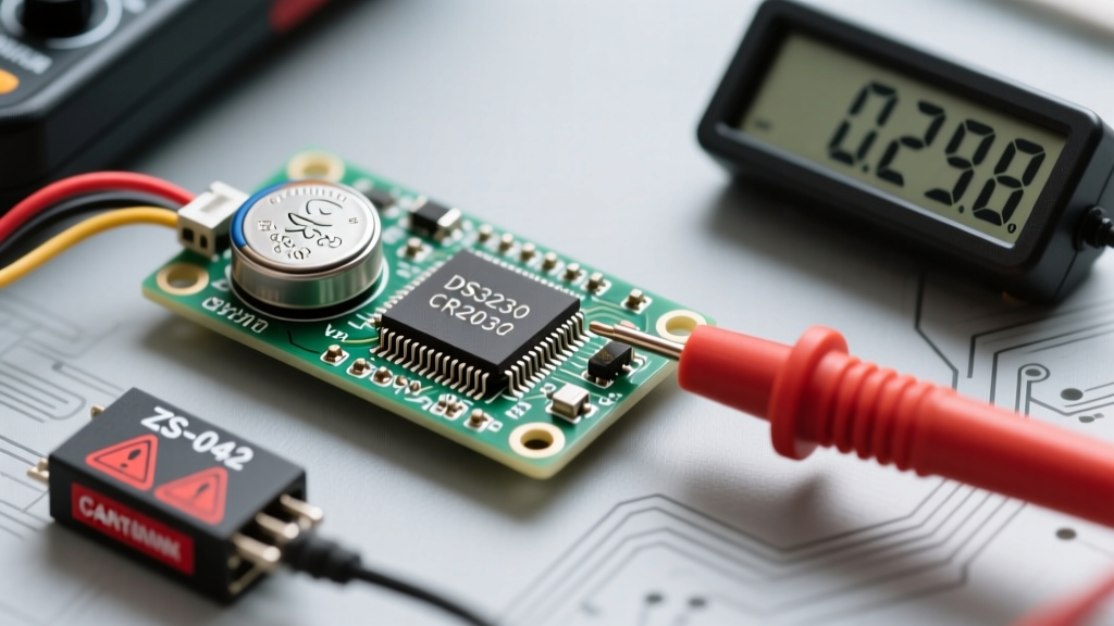
The ZS-042 module was originally designed to use an LIR2032 battery, which is a rechargeable 3.6V lithium-ion coin cell. To support this, the ZS-042 includes a rudimentary charging circuit consisting of a 1N4148 diode and a 200Ω surface-mount resistor connected between the VCC (5V) line and the battery holder. If you insert a standard, non-rechargeable CR2032 (3.0V primary lithium cell) into a ZS-042 module and power the board via 5V, the circuit will attempt to force current into the primary cell. This causes the CR2032 to overheat, vent toxic gas, swell, and potentially rupture or explode.
Safety Warning: Never use a standard CR2032 battery in an unmodified ZS-042 rtc module ds3231. If you must use a CR2032 for its superior capacity and shelf life, you must physically disable the charging circuit.
How to Disable the ZS-042 Charging Circuit
To safely use a CR2032 on the ZS-042, take a soldering iron and desolder either the 1N4148 diode (labeled D1) or the 200Ω resistor located near the battery holder. Breaking this path prevents VCC from back-feeding into the battery. Alternatively, you can simply snip the diode with flush cutters. Once modified, the ZS-042 behaves identically to the HW-111 module, safely trickle-powering the RTC from the CR2032 when main power is lost.
I2C Bus Lockups and Address 0x68 Conflicts
The DS3231 communicates via the I2C protocol, and its hardware address is hardcoded to 0x68. If your microcontroller fails to initialize the rtc module ds3231, or if the I2C bus locks up entirely, the issue usually lies in pull-up resistor sizing or address collisions.
The AT24C32 EEPROM Ghost
Most DS3231 modules include an onboard AT24C32 EEPROM chip for data logging. This chip sits on the exact same I2C bus but uses the address 0x57. When running an I2C scanner sketch (like the standard Arduino Wire scanner), beginners often panic seeing two devices and assume the RTC is faulty. Seeing both 0x68 and 0x57 is the expected behavior for a fully populated module.
Pull-Up Resistor Diagnostics
The DS3231 features open-drain I2C pins. It cannot drive the SDA and SCL lines HIGH on its own; it can only pull them LOW. If your microcontroller board lacks internal pull-ups, or if you have multiple devices dragging the bus capacitance too high, the signals will degrade into sawtooth waves, causing data corruption.
- Standard Mode (100kHz): Requires 4.7kΩ pull-up resistors on both SDA and SCL to VCC (3.3V or 5V).
- Fast Mode (400kHz): Requires 2.2kΩ pull-up resistors to overcome bus capacitance and achieve sharp rise times.
If your I2C bus hangs after a system reset, measure the SDA and SCL lines with a multimeter. If they are floating near 1.5V instead of sitting firmly at VCC, your pull-ups are missing or insufficient. Consult the Arduino Wire Library documentation for software-level I2C timeout handling to prevent permanent bus lockups.
VBAT Diagnostics and Parasitic Power Drain
A frequent complaint among field engineers is that the CR2032 battery on the rtc module ds3231 dies in a matter of weeks, rather than the expected 5+ years. This is almost always caused by parasitic power drain through the I2C bus or a faulty module design.
The SDA/SCL Backfeed Problem
When your main microcontroller goes to sleep or powers down, its I2C pins might remain HIGH (pulled up to 3.3V). Because the DS3231 has internal ESD protection diodes connecting the I/O pins to the VCC pin, current will flow from the SDA/SCL lines, through the ESD diodes, and into the VCC pin. This 'parasitic power' forces the DS3231 into a weird semi-powered state. It draws heavily from the VBAT (coin cell) pin as the internal power multiplexer struggles to decide between the phantom VCC voltage and the legitimate VBAT voltage.
The Fix: Ensure that when your system powers down, the I2C pull-up resistors are also disconnected from the power rail, or configure your microcontroller's I2C pins as INPUT (High-Z) before entering deep sleep. For detailed power multiplexer logic, refer to the Analog Devices DS3231 Datasheet.
DS3231 Troubleshooting Quick-Reference Matrix
Use the following diagnostic matrix to isolate faults on your rtc module ds3231 quickly.
| Symptom | Root Cause | Hardware / Software Fix |
|---|---|---|
| Battery swells / gets hot | ZS-042 charging circuit active with CR2032 | Desolder D1 diode or 200Ω resistor on module |
| Time resets to Jan 1, 2000 on power loss | Dead CR2032 or VBAT trace severed | Test VBAT voltage (must be >2.5V); check battery holder tension |
| I2C Scanner shows no devices | Missing pull-ups or SDA/SCL swapped | Add 4.7kΩ pull-ups; verify wiring against board silkscreen |
| Time drifts by seconds per day | Module exposed to extreme thermal gradients | Move module away from heat sources (voltage regulators, motors) |
| SQW pin reads random HIGH/LOW | Floating open-drain interrupt pin | Add 10kΩ pull-up resistor to SQW/INT pin |
Decoding Temperature and Aging Registers
If your rtc module ds3231 is still exhibiting slight drift (e.g., losing 2 seconds a month) despite having a healthy battery and stable I2C communication, you can manually calibrate the silicon using the internal registers. The DS3231 continuously monitors its internal die temperature and adjusts the oscillator capacitor bank accordingly.
You can read the exact internal temperature via Register 0x11 (Temperature MSB/LSB). The resolution is 0.25°C. If your module is placed inside a sealed enclosure that traps heat, the TCXO will compensate for the internal die temperature, which may differ from the ambient room temperature you expect.
Furthermore, you can manually tweak the Aging Offset Register (0x10). This register allows you to add or subtract capacitance to the oscillator bank in software. If your clock runs consistently fast, writing a negative two's complement value to Register 0x10 will slow it down. This level of granular control is what makes the Adafruit DS3231 Precision RTC Breakout and similar high-quality implementations so valuable for precision data logging applications.
Final Verification Steps
Before deploying your rtc module ds3231 into a permanent installation, run a 48-hour burn-in test. Log the I2C bus state, the VCC voltage, and the internal temperature register every 60 seconds to an SD card or serial monitor. This will expose any marginal solder joints, thermal drift issues, or parasitic power drains before the system is sealed inside an enclosure. Proper hardware vetting and an understanding of the I2C bus physics will ensure your timekeeping remains flawless for years.