
The Hidden Dangers of Voltage Testing
Checking voltage is the most fundamental task in electrical diagnostics, yet it remains one of the most dangerous. According to OSHA's electrical safety standards, a significant percentage of electrical fatalities occur during routine testing and troubleshooting. When you are learning how to use a multimeter to check voltage, the focus is often entirely on the reading on the screen. However, from a professional safety perspective, the physical act of probing a live circuit introduces severe risks, including arc flash, equipment explosion, and fatal shock.
To mitigate these risks, electricians and advanced DIYers must adopt rigorous safety frameworks. This guide moves beyond basic dial settings and dives deep into the critical safety protocols, equipment ratings, and procedural habits required to measure voltage in high-energy environments without compromising your life or your equipment.
Decoding Multimeter CAT Ratings Before You Test
The most common point of failure in voltage testing is using a multimeter with an inadequate Measurement Category (CAT) rating for the environment. A CAT rating does not merely indicate the maximum steady-state voltage the meter can handle; it defines the meter's ability to withstand high-energy impulse transients (voltage spikes) that occur in specific electrical zones.
For example, a CAT II 600V meter and a CAT III 600V meter are both rated for 600 volts of continuous voltage. However, the CAT III meter is tested to withstand an 8,000V impulse transient, whereas the CAT II meter is only tested to 4,000V. If you take a CAT II meter to a commercial distribution panel (a CAT III environment) and a heavy inductive load switches off, the resulting transient can arc across the meter's internal gaps, causing the casing to explode in your hands. For a comprehensive breakdown, refer to Fluke's comprehensive guide on Measurement Categories.
CAT Rating Application Matrix
| Category | Environment Description | Example Test Points | Impulse Withstand (at 600V) |
|---|---|---|---|
| CAT II | Local level, plug-in loads | Standard wall outlets, appliances, portable tools | 4,000V |
| CAT III | Distribution level, fixed wiring | Panel boards, circuit breakers, heavy commercial lighting | 8,000V |
| CAT IV | Utility level, origin of installation | Main service entrances, utility meters, outdoor drop lines | 12,000V |
Phase 1: Pre-Test Equipment and Probe Inspection
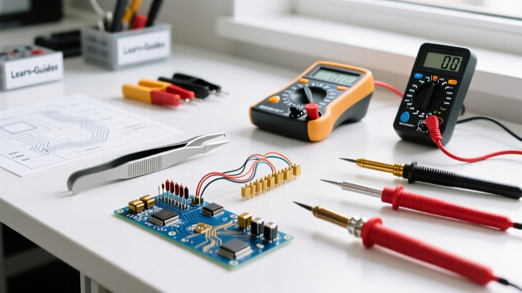
Before you even turn the multimeter dial, you must inspect your test leads. The test leads are your primary insulation barrier between your body and lethal voltage. Under the NFPA 70E Standard for Electrical Safety in the Workplace, damaged test equipment must be immediately removed from service.
- Insulation Integrity: Run your fingers along the entire length of the probe wires. Look for micro-cracks, dry rot, or exposed copper strands. Even a tiny crack can allow an arc to track across your skin in humid conditions.
- Tip Exposure (GS38 Compliance): Standard probes often expose 19mm of metal at the tip. In tight panels, this creates a massive short-circuit hazard if the probe slips across busbars. Always use shrouded tips or probes with a maximum 4mm exposed tip (compliant with GS38 guidance) when working inside live distribution panels.
- Internal Fuses: Ensure your meter utilizes High Rupturing Capacity (HRC) ceramic fuses filled with sand. Cheap glass fuses will not stop a high-energy fault and can turn the multimeter into a fragmentation grenade.
Phase 2: The Live-Dead-Live (LDL) Verification Protocol
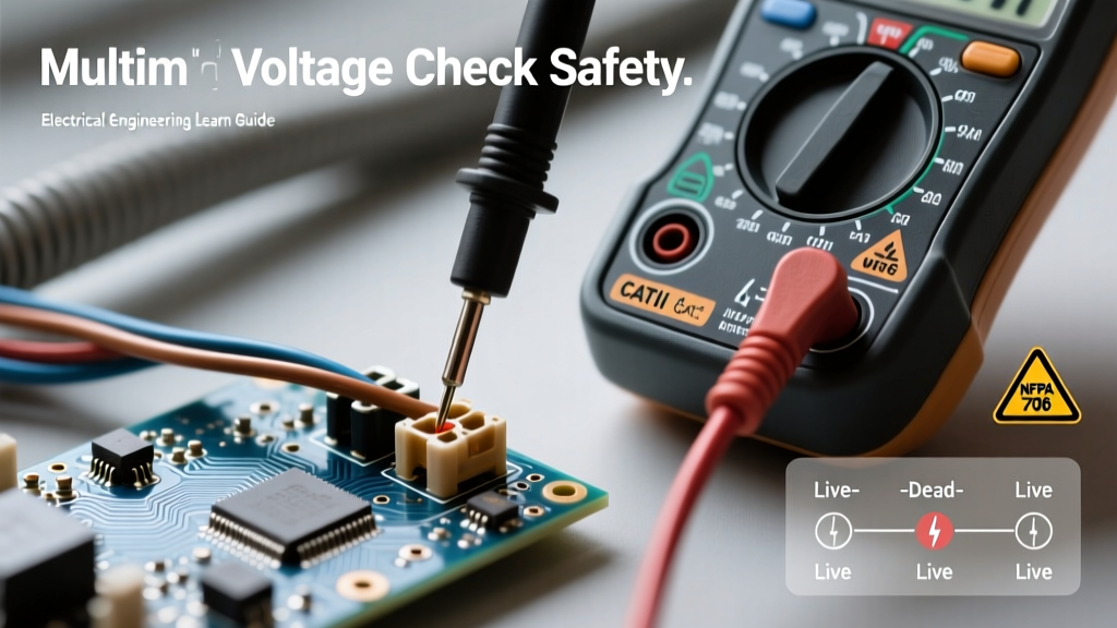
When verifying that a circuit is de-energized before touching it, you must never simply probe the target wires and trust a '0.0V' reading. A dead battery, a blown internal fuse, or a broken wire inside the test lead will also result in a '0.0V' reading on a live circuit. To prevent this fatal assumption, professionals use the Live-Dead-Live (LDL) protocol.
- Live (Proving Unit): Test your multimeter on a known, verified live voltage source (or a dedicated voltage proving unit) to confirm the meter and leads are functioning correctly and displaying the expected voltage.
- Dead (Target Circuit): Test the target circuit you intend to work on. Verify phase-to-phase and phase-to-ground for all conductors. The reading must be zero.
- Live (Proving Unit Again): Immediately return to the known live source to re-verify the meter. This proves that the meter did not fail, lose battery power, or blow a fuse during the exact window you were testing the target circuit.
Phase 3: Executing the Measurement Safely
Once the circuit is confirmed live and you are taking operational voltage readings, your physical technique becomes your last line of defense.
The One-Hand Rule
When probing live terminals, keep one hand behind your back or in your pocket. If you use two hands and accidentally touch a live conductor with your left hand and a grounded surface with your right, the current will travel across your chest, directly through your heart. This hand-to-hand pathway can induce ventricular fibrillation at currents as low as 30mA to 50mA. By keeping one hand away from the panel, you force any accidental shock to travel from hand-to-foot or hand-to-same-hand, which, while still dangerous and capable of causing severe burns, is statistically less likely to cause immediate cardiac arrest.
Visual Targeting and Tactile Guards
Never look down at the multimeter screen while your probe tips are making contact with the terminals. Your eyes must remain locked on the probe tips to prevent accidental slipping. Ensure your fingers are positioned strictly behind the tactile raised guard on the probe body. If a high-energy arc flash occurs, the tactile guard prevents your fingers from sliding forward and contacting the energized metal tip.
Troubleshooting Phantom Voltage and False Readings
In modern electrical systems with dense conduit runs, you may encounter 'phantom voltage' or 'ghost voltage.' This occurs when an unenergized wire runs parallel to a live wire for a long distance, acting as a capacitor and inducing a false voltage reading (often between 20V and 80V on a 120V circuit).
Standard digital multimeters have an extremely high input impedance (typically 10 Megohms) to prevent loading the circuit. However, this high impedance makes them highly sensitive to capacitive coupling. To safely and accurately verify if a voltage is real or phantom, switch your multimeter to the LoZ (Low Impedance) mode if equipped (like the Fluke 117). LoZ mode drops the input impedance to roughly 3 kilohms, bleeding off the phantom capacitive charge and dropping the reading to a true zero. If you are using a standard meter without LoZ, paralleling a small incandescent test lamp or a solenoid voltage tester (Wiggy) across the terminals will safely drain the phantom charge and reveal the true state of the circuit.
Safety Maxim: 'Test Before Touch' is not just a slogan; it is a strict procedural mandate. Never assume a circuit is dead based on the position of a wall switch, a tripped breaker label, or the absence of hum. Always verify with a properly rated, pre-tested multimeter.
Summary Checklist for High-Voltage Environments
Before your next voltage diagnostic, run through this mental checklist to ensure maximum safety and data integrity:
- [ ] Is my multimeter CAT rated for the specific panel/environment I am opening?
- [ ] Are my test leads free of cracks and equipped with appropriate tip shrouding?
- [ ] Have I donned the correct PPE (Arc-rated clothing, voltage-rated gloves with leather protectors, and face shield) as dictated by the panel's incident energy label?
- [ ] Am I prepared to execute the Live-Dead-Live protocol?
- [ ] Have I positioned my body to utilize the one-hand rule and maintain my arc flash boundary?
Mastering how to use a multimeter to check voltage is a blend of technical knowledge and uncompromising safety discipline. By respecting the energy present in electrical systems and relying on verified protocols, you ensure that every diagnostic task ends with accurate data and, more importantly, a safe return home.