
The Silicon Reality: Beyond the Mechanical Wiper
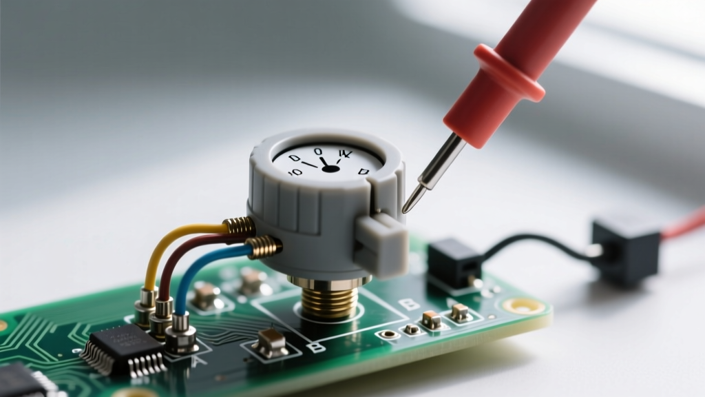
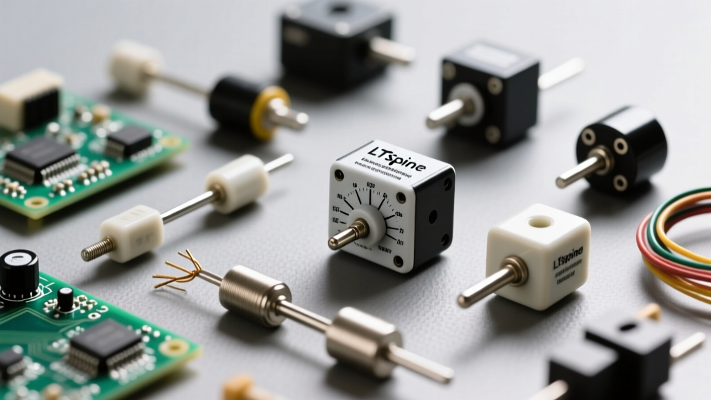
When transitioning from mechanical variable resistors to solid-state alternatives, engineers often assume a digital potentiometer (digipot) is simply a drop-in replacement. This assumption leads to catastrophic circuit failures, unexpected non-linearities, and burnt-out ICs. A digital potentiometer is not a passive component; it is an active, mixed-signal CMOS integrated circuit that emulates resistive behavior using an internal resistor ladder and an array of electronic switches. Understanding the internal architecture, wiper resistance limitations, and strict voltage rail boundaries is mandatory for successful integration into modern microcontroller-driven designs.
Decoding the Resistor String Architecture
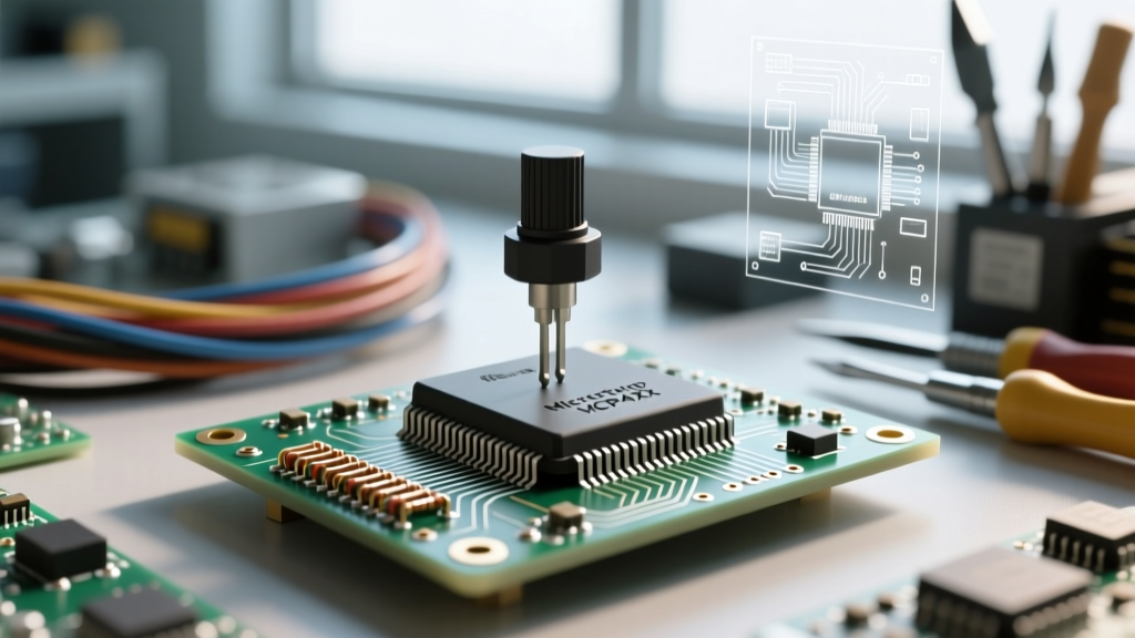
At the core of nearly all modern digipots is the resistor string architecture. Unlike the R-2R ladder networks used in digital-to-analog converters (DACs), a digipot utilizes a series chain of identical polysilicon or thin-film resistors. For an 8-bit device (like the ubiquitous Microchip MCP41010), there are 256 individual resistor segments connected in series between the high terminal (RH) and the low terminal (RL).
Connecting to the nodes between these resistors is a matrix of CMOS transmission gates (switches). When a digital command is received via a serial interface, the internal decoder closes exactly one switch, connecting the wiper terminal (RW) to a specific tap point on the string. According to the Microchip MCP41xxx Datasheet, this architecture ensures excellent ratio-metric stability over temperature, even if the absolute end-to-end resistance varies by up to 20% from batch to batch.
The Hidden Wiper Resistance (Rw) Trap
The most common point of failure in digipot circuit design is ignoring the wiper resistance, denoted as Rw in datasheets. Because the wiper connects to the resistor string through a physical CMOS switch, it introduces an unavoidable series resistance.
- Ideal Mechanical Pot: Wiper resistance is negligible (typically < 1Ω).
- Solid-State Digipot: Wiper resistance ranges from 40Ω to over 400Ω, depending on the specific IC and supply voltage.
If you configure a 10kΩ 8-bit digipot as a rheostat (variable resistor) by tying the wiper to one of the end terminals, you might expect the resistance to range from 0Ω to 10kΩ. In reality, the minimum resistance will never drop below Rw (e.g., 75Ω). Furthermore, because Rw is highly non-linear and varies with the applied voltage and temperature, using a digipot as a rheostat in high-precision analog paths introduces severe thermal drift. As detailed in the Analog Devices Tutorial MT-023, digipots should almost always be used in voltage divider (potentiometer) mode, where the load impedance is significantly higher than the end-to-end resistance, effectively masking the Rw non-linearity.
Protocol Selection: SPI, I2C, and Pulse-Count Interfaces
Digital potentiometers are available with several distinct communication interfaces, each dictating the physical layout and microcontroller overhead required for operation.
Comparative Analysis of Popular Digipot ICs
| IC Model | Interface | Memory Type | Resolution | Best Use Case |
|---|---|---|---|---|
| Microchip MCP41010 | SPI | Volatile (RAM) | 8-bit (256 steps) | High-speed runtime tuning, audio pre-amps |
| Analog Devices AD5254 | I2C | Non-Volatile (EEPROM) | 8-bit (Quad Channel) | Factory calibration, sensor offset trimming |
| Renesas X9C103 | Up/Down (Pulse) | Non-Volatile (EEPROM) | 100 taps | Simple logic control, push-button interfaces |
For closed-loop PID control systems or audio volume automation, volatile SPI/I2C devices are mandatory. Non-volatile EEPROM-based digipots are designed for 'set-and-forget' calibration. Writing to the EEPROM cells continuously will destroy the IC; most manufacturers guarantee a maximum of 1,000,000 write cycles. If a microcontroller updates an EEPROM-backed digipot at 10Hz, the memory will wear out in roughly 27 hours.
The Absolute Maximum Ratings: Voltage Rail Boundaries
A mechanical potentiometer is completely agnostic to the voltage applied across its terminals; you can safely place 100V across a 10kΩ mechanical pot rated for 0.5W. A digital potentiometer, however, is bound by its silicon substrate and power supply rails.
Critical Design Rule: The analog signals present at RH, RL, and RW must never exceed the digipot's VDD and VSS (or GND) pins by more than 0.3V. Exceeding these rails forward-biases internal parasitic ESD protection diodes, resulting in severe signal clamping, massive total harmonic distortion (THD), or permanent latch-up destruction of the CMOS die.
If you need to control an analog signal that swings between -12V and +12V, a standard 5V digipot will instantly fail. To handle bipolar or high-voltage signals, you must either use specialized high-voltage digipots (which are expensive and have limited resolution) or design an external opto-isolated or relay-switched resistor network. Alternatively, you can use the digipot to control the reference voltage of an operational amplifier circuit, keeping the high-voltage signal strictly within the op-amp's feedback loop while the digipot operates safely at low-voltage DC levels.
Handling AC Signals and Parasitic Capacitance
Passing alternating current (AC) signals, such as audio waveforms, through a digital potentiometer requires careful DC biasing. Because the internal CMOS switches cannot pass voltages below the VSS pin (usually 0V/GND), an audio signal centered at 0V will be brutally half-wave rectified by the internal switch architecture. To pass AC signals cleanly, the entire waveform must be DC-biased to sit exactly midway between VSS and VDD (e.g., biased at 2.5V on a 5V supply). Capacitors must then be used at the input and output to block this DC offset from affecting adjacent circuit stages.
Furthermore, the physical geometry of the 256 CMOS switches introduces parasitic capacitance. When combined with the polysilicon resistor string, this creates an unintentional distributed low-pass filter. A 100kΩ digital potentiometer may exhibit a -3dB bandwidth of only a few hundred kilohertz. For RF applications or high-speed video signal routing, the parasitic capacitance will severely attenuate high-frequency harmonics, making digipots unsuitable for anything beyond audio frequencies or slow DC trimming.
Wiper Glitches and Make-Before-Break Transitions
When the digital code changes from one tap to an adjacent tap, the internal decoder must turn off one CMOS switch and turn on the next. The timing of this transition is critical. Older or cheaper digipot architectures use a 'break-before-make' sequence, where the wiper momentarily disconnects from the resistor string entirely during the transition. In a voltage divider configuration, this causes the wiper to float, resulting in a massive voltage glitch that can spike downstream analog-to-digital converters (ADCs) or cause audible 'pops' in audio amplifiers.
Modern precision digipots utilize a 'make-before-break' architecture. The new switch closes before the old switch opens, ensuring continuous connectivity. However, this temporarily places two adjacent resistor segments in parallel, causing a momentary, slight dip in resistance. While vastly superior to floating glitches, sensitive sample-and-hold circuits must still be designed to ignore the wiper output during the exact microsecond the SPI/I2C command is clocked into the device.