
The Anatomy of a Potentiometer: Beyond the Knob
Potentiometers, affectionately known as 'pots' in the DIY electronics community, are foundational components used in everything from custom audio amplifiers to DIY motor speed controllers. Whether you are holding a rugged, cermet-trimmer like the Bourns 3386 series or a panel-mount carbon-track Alps RK09, the fundamental operation remains identical. However, staring at the three metal terminals on the back of the casing can cause confusion for beginners. Understanding the exact function of the pins on a potentiometer is the critical first step to designing noise-free, reliable circuits.
At its core, a potentiometer is a mechanically actuated variable resistor. It consists of a resistive element (the track) and a sliding contact (the wiper). The physical pins on the casing are the electrical bridges that connect your circuit to these internal elements. Misidentifying these pins doesn't necessarily mean your circuit will explode, but it will result in reversed controls, erratic voltage drops, or a complete failure to adjust the signal.
Decoding the Pins on a Potentiometer
Standard mechanical potentiometers feature exactly three pins. While their physical layout might vary depending on whether the pot is a single-turn, multi-turn, or slider variant, their electrical roles are universal.
Pin 1 and Pin 3: The Fixed Resistance Terminals
Pins 1 and 3 connect to the opposite ends of the internal resistive track. If you are working with a standard 10KΩ potentiometer, measuring the resistance between Pin 1 and Pin 3 with a multimeter will yield approximately 10,000 ohms, regardless of where the shaft is positioned. These pins define the total, fixed resistance of the component. Swapping Pin 1 and Pin 3 in your circuit will not break the component, but it will reverse the directional behavior of the knob (e.g., turning the knob clockwise will decrease resistance instead of increasing it).
Pin 2: The Wiper (The Magic Terminal)
Pin 2 is connected to the wiper, the physical metal or carbon brush that slides along the resistive track as you turn the shaft. This is the most critical of the pins on a potentiometer. The wiper divides the total resistance into two varying, complementary segments. As the wiper moves closer to Pin 1, the resistance between Pin 1 and Pin 2 drops toward zero, while the resistance between Pin 2 and Pin 3 approaches the maximum rated value. In high-quality pots, the wiper contact resistance is typically under 1Ω, though cheaper carbon-track pots may exhibit up to 3Ω of contact resistance, which can introduce thermal noise in sensitive audio preamps.
Wiring Configurations: Voltage Divider vs. Rheostat
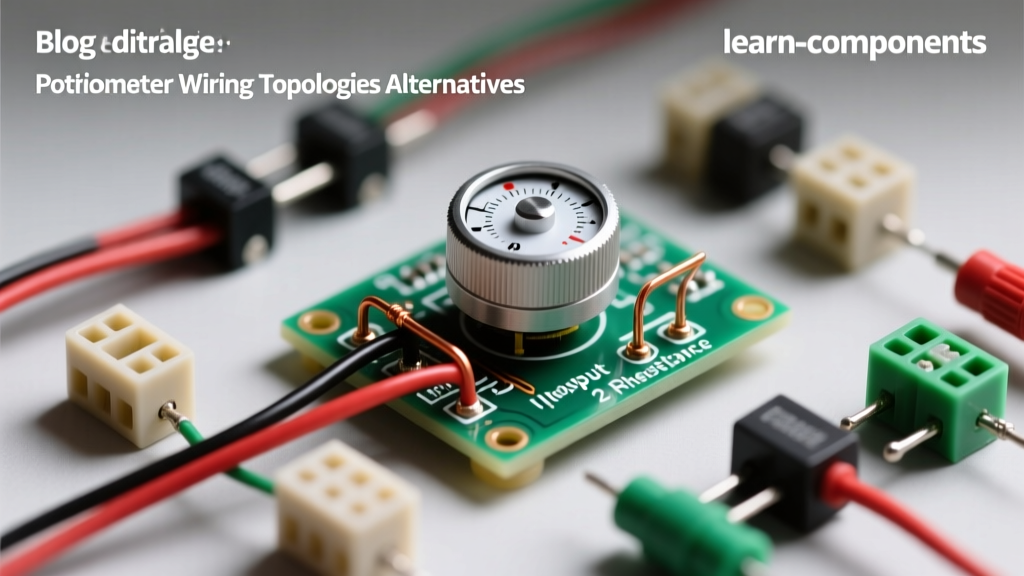
How you utilize the pins on a potentiometer dictates its function in your circuit. There are two primary wiring topologies used in prototyping and PCB design.
| Configuration | Pin 1 (CCW) | Pin 2 (Wiper) | Pin 3 (CW) | Primary Use Case |
|---|---|---|---|---|
| Voltage Divider | Connected to GND | Output (V_out) | Connected to V_in | Reading analog sensors, audio volume control, setting bias voltages. |
| Variable Resistor (Rheostat) | Connected to Pin 2 | Circuit Path | Floating or connected to Pin 2 | Dimming LEDs, adjusting op-amp gain, motor speed control. |
When wiring a pot as a voltage divider, you apply a reference voltage across Pins 1 and 3, and read the divided voltage from Pin 2. This is how microcontrollers like the Arduino read analog inputs. When wiring as a rheostat, you only use two pins in the circuit path: the wiper (Pin 2) and one of the outer pins. Tying the unused outer pin directly to the wiper pin is a best practice; if the wiper momentarily loses contact due to dirt or vibration, the circuit defaults to the maximum resistance rather than floating into an open-circuit state.
Taper and Wiper Voltage: Linear vs. Logarithmic
The physical layout of the pins remains the same across different tapers, but the internal geometry of the resistive track changes how the voltage at Pin 2 behaves relative to the shaft angle. A Linear taper (often marked with a 'B', such as B10K) features a uniform resistive track. At the 50% rotation mark, the resistance between Pin 1 and Pin 2 will be exactly half of the total resistance. Conversely, an Audio or Logarithmic taper (marked with an 'A', like A10K) features a compressed track on one side and an expanded track on the other. This mimics the non-linear way human ears perceive loudness, making it mandatory for the pins on a potentiometer used in audio volume stages to follow this curve to avoid 'all-or-nothing' volume jumps.
Physical vs. Digital: A Pinout Comparison
As prototyping evolves, many DIYers are replacing mechanical pots with digital potentiometers controlled via microcontrollers. It is vital to contrast the physical pins on a standard potentiometer with the pins on a digital IC like the Microchip MCP4131. A mechanical pot requires no power supply; its pins simply pass current through a physical medium. A digital pot, however, requires VDD, VSS, and digital communication pins (SPI or I2C). While a mechanical pot handles high-current AC/DC signals natively (up to its power rating, typically 0.2W to 0.5W), digital pots are strictly limited to low-voltage DC signals within their supply rails, making them unsuitable for direct high-power audio amplification but perfect for precision programmable gain amplifiers.
Real-World Troubleshooting: Testing Potentiometer Pins
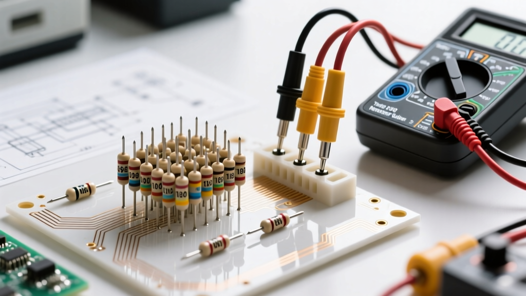
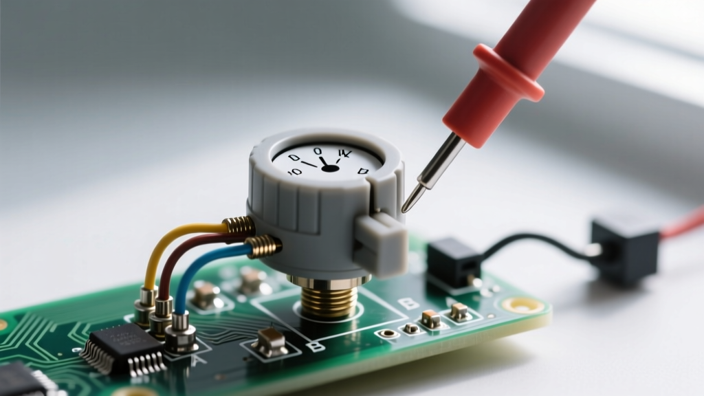
Before soldering a potentiometer to your PCB or perfboard, always verify the pinout and health of the track using a digital multimeter (DMM). Follow this exact sequence to verify the pins on a potentiometer:
- Identify Total Resistance: Set your DMM to the Ohms (Ω) setting. Place probes on Pin 1 and Pin 3. The reading should match the rated value of the pot (e.g., ~10KΩ) within a 10% to 20% tolerance.
- Test the Wiper Track: Move one probe to Pin 2 (the wiper), keeping the other on Pin 1. Slowly rotate the shaft from one extreme to the other. The resistance should sweep smoothly from near 0Ω to the maximum rated value.
- Check for Dead Spots: Repeat the previous step, but place the probes on Pin 2 and Pin 3. As you sweep the knob, watch the DMM display closely. Any sudden jumps, infinite readings, or erratic fluctuations indicate physical damage or contamination on the resistive track.
Common Failure Modes at the Pin and Wiper Junction
Understanding how the pins on a potentiometer fail is crucial for long-term DIY project reliability. The most common failure is 'wiper bounce' or scratchy audio noise, caused by carbon dust or oxidation accumulating between the wiper brush and the track. In high-vibration environments (like guitar pedals or automotive dashboards), the mechanical crimps that connect the internal track to the external pins can fracture, leading to an open circuit. Furthermore, exceeding the power rating of the pot (usually 0.5W for standard 16mm pots) will cause thermal runaway, literally burning the resistive carbon or cermet material away from the pin junctions.
Expert Prototyping Tip: If a mechanical potentiometer exhibits scratchy noise or dead spots during the wiper sweep, do not immediately discard it. Injecting a small amount of DeoxIT D5 contact cleaner into the wiper slot and rotating the shaft 50 times can dissolve carbon buildup and restore perfect pin-to-track conductivity in 90% of cases.
By mastering the specific roles, wiring topologies, and failure modes of the pins on a potentiometer, you elevate your prototyping from guesswork to precision engineering. For deeper theoretical insights into variable resistors and rheostat configurations, consult the comprehensive guides at All About Circuits or review specific mechanical tolerances in the Bourns 3386 Datasheet.