
Beyond the Dictionary: How to Define Potentiometer Requirements
When prototyping a new circuit or transitioning a design to mass production, simply searching a distributor's database for a 'variable resistor' is a recipe for BOM (Bill of Materials) errors. To properly define potentiometer parameters for your project, you must look far beyond the basic resistance value. A potentiometer is fundamentally a three-terminal resistor with a sliding or rotating contact that forms an adjustable voltage divider. However, from a procurement and engineering perspective, defining a potentiometer means mapping electrical tolerances, mechanical lifespans, and environmental seals to your specific application.
Whether you are designing a high-fidelity audio mixer, a rugged industrial control panel, or a precision sensor calibration circuit, this guide will help you navigate the critical specifications required to select the perfect component.
The Engineering Definition vs. The Buyer's Definition
According to foundational electronics texts like those at All About Circuits, a potentiometer divides voltage based on the physical position of the wiper. But for a hardware buyer, the definition expands into three distinct categories: Electrical Characteristics (taper, power, TCR), Mechanical Form Factor (bushing size, shaft type, travel angle), and Reliability Metrics (rotational life, IP rating, contact resistance).
Electrical Parameters: Mapping the Track and Wiper
Resistance Taper Curves (A, B, and W)
The taper defines how the resistance changes relative to the shaft's physical rotation. Misidentifying the taper is the most common mistake in audio and UI design.
- Linear (B-Taper): Resistance changes at a constant rate. Essential for voltage dividers, sensor calibration, and analog joystick positioning. (e.g., B10K).
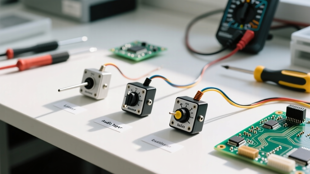
- Logarithmic / Audio (A-Taper): Resistance changes slowly at first, then rapidly. This mimics the human ear's non-linear perception of loudness. Mandatory for audio volume controls. (e.g., A50K).
- Reverse Logarithmic (C or W-Taper): The inverse of the A-taper, often used in specific tone-control circuits or reverse-gain staging.
Power Dissipation and the 'Rheostat Trap'
Potentiometers typically range from 0.05W (for surface-mount trimpots) up to 5W or more for chassis-mount wirewound power resistors. A critical design rule: power ratings assume the entire resistive track is in the circuit.
Expert Warning: The Rheostat Trap. If you wire a potentiometer as a two-terminal variable resistor (rheostat) to control current, the power dissipation concentrates on a smaller segment of the track, leading to thermal runaway and track burnout. Furthermore, if the wiper loses contact, the circuit becomes an open loop (infinite resistance). Always tie the wiper to the unused third terminal; this ensures that if the wiper fails, the circuit defaults to maximum resistance rather than an open circuit.
Material Science: Cermet vs. Carbon vs. Conductive Plastic
The resistive element's material dictates the component's lifespan, noise floor, and temperature stability. When you define potentiometer materials, consult the Bourns Potentiometer Catalog or similar manufacturer matrices to match the material to your use case.
| Material Type | Typical Lifespan | TCR (ppm/°C) | Best Application | Example Series |
|---|---|---|---|---|
| Carbon Composition | 15,000 - 30,000 cycles | ±1000 | Low-cost consumer electronics, basic UI | Panasonic EVU series |
| Cermet (Ceramic-Metal) | 200 - 1,000 cycles | ±100 | PCB trimpots, one-time calibration | Bourns 3296 / 3386 |
| Conductive Plastic | 1,000,000+ cycles | ±200 | High-end audio faders, studio equipment | Alps Alpine RK09K |
| Wirewound | 100,000 cycles | ±50 | High-power motor control, heavy machinery | Vishan 534 series |
Application-Specific Selection Matrix
Use this decision framework to rapidly define potentiometer requirements based on your end-product environment.
| Application Scenario | Recommended Form Factor | Required Specs & Features |
|---|---|---|
| Audio Volume Control (Panel Mount) | Rotary, 8mm or 9mm shaft | A-Taper (Log), Conductive Plastic, low wiper noise (<50mV) |
| PCB Sensor Calibration (Factory) | Multi-turn Trimpot (Top/Side adjust) | B-Taper (Linear), Cermet, 10-25 turns for fine resolution |
| Industrial Valve Positioning | Chassis Mount Wirewound | B-Taper, IP67 Sealed, High Power (3W+), Ball-bearing shaft |
| Portable Synth / MIDI Controller | Slide Fader (Linear travel) | B-Taper, Carbon or Conductive Plastic, 30mm-60mm travel |
Mechanical Form Factors and Panel Integration
Electrical specs mean nothing if the component doesn't physically mate with your enclosure. When defining the mechanical parameters, pay strict attention to the mounting hardware.
Shaft Types and Bushing Lengths
- Round Shafts: Require set-screw knobs. Common in 6mm (metric) and 1/4-inch (imperial) diameters.
- D-Shafts: Feature a flat side to prevent knob slippage without needing a set-screw. Standard in consumer appliances.
- Knurled / Split Shafts: Designed for push-on friction-fit knobs. Standard in guitar amplifiers and audio gear (typically 6mm with 18 or 24 splines).
Equally critical is the bushing length. If your front panel is 4mm thick, a standard 7mm bushing will barely allow the nut to thread. Always specify bushing length relative to your panel thickness plus any washers or lock-nuts required.
Real-World Failure Modes and Reliability Data
To truly define potentiometer reliability, you must anticipate how the component will fail in the field. Signal chain engineers at Texas Instruments frequently note that variable resistors are the primary source of analog noise in aging equipment.
Contact Resistance and Wiper Noise
Over time, dust, oxidation, and mechanical wear create micro-gaps between the wiper and the resistive track. This manifests as 'scratchy' audio or erratic ADC (Analog-to-Digital Converter) readings in microcontrollers. To mitigate this:
- Specify a sealed enclosure (e.g., Bourns' sealed cermet trimpots) if the device will operate in high-humidity or dusty environments.
- Look for multi-finger wipers in the datasheet. Wipers with 3 or 4 contact fingers bridge micro-gaps, ensuring continuous electrical contact even if one finger encounters track debris.
- For microcontroller inputs, always add a hardware low-pass RC filter or implement a software moving-average filter to debounce wiper noise.
Environmental Sealing (IP Ratings)
Standard rotary pots are rarely waterproof. If your HMI (Human-Machine Interface) requires washdown capabilities (e.g., marine electronics or food processing), you must define potentiometer IP ratings. Look for components rated IP64 or higher, which utilize internal O-rings and silicone boots to prevent moisture ingress into the resistive cavity.
Finalizing Your BOM: Procurement Tips
When finalizing your selection, avoid generic, unbranded potentiometers from unknown marketplace sellers for production runs. The resistance tolerance on cheap carbon pots can drift up to ±30% between batches, which will ruin automated calibration routines. Stick to established manufacturers like Bourns, Alps Alpine, Vishay, and Panasonic. Always order sample kits to test the 'feel' (rotational torque) and taper curve in-circuit before committing to a 10,000-unit reel.