
Decoding the Datasheet: Why Your Potentiometer Readings Drift
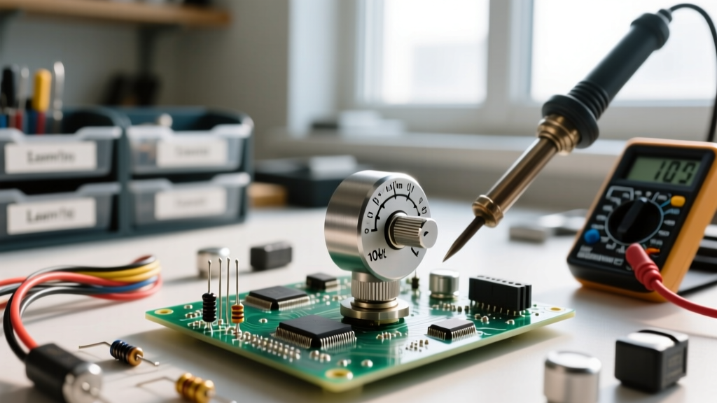
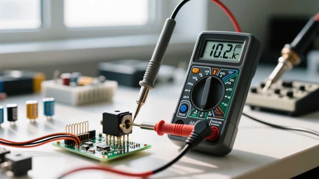
When prototyping analog interfaces, erratic or non-linear potentiometer readings are a common source of frustration. You might wire up a 10kΩ trimmer to an Arduino or a precision 12-bit ADC, only to find the digital values jumping unpredictably or stalling at the extremes of the rotation. While it is tempting to blame the microcontroller's ADC, the root cause usually lies in a misunderstood datasheet specification. Potentiometers are not ideal resistors; they are electromechanical devices with physical limitations, thermal drift, and complex wiper dynamics.
In this datasheet breakdown, we will dissect the critical parameters found in industry-standard component sheets—such as the Bourns 3296 Cermet Trimpot and wirewound precision pots. By understanding Contact Resistance Variation (CRV), taper laws, and resolution limits, you can design circuits that yield rock-solid potentiometer readings every time.
The Core Parameters Affecting Multimeter and ADC Readings
Before soldering a potentiometer to your PCB, you must evaluate four specific datasheet columns that directly dictate the quality of your analog voltage divider output:
- Total Resistance Tolerance: Usually ±10% or ±20%. This affects the absolute resistance but not the linearity of the sweep.
- Independent Linearity: The maximum deviation from a straight line drawn between the actual zero and full-scale resistance points.
- Contact Resistance Variation (CRV): The dynamic noise generated as the wiper moves.
- Wiper Contact Resistance: The static parasitic resistance between the wiper terminal and the resistive track.
Taper (Law) Curves: Linear vs. Audio vs. Logarithmic
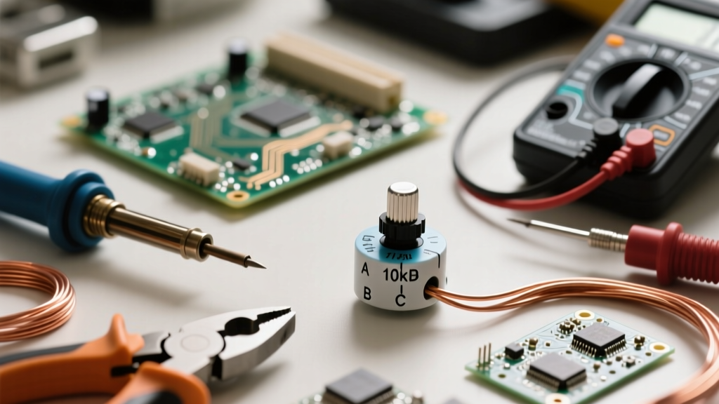
The most frequent cause of skewed potentiometer readings in DIY and prototyping environments is selecting the wrong taper. The taper defines the mathematical relationship between the mechanical shaft rotation and the resistance output. Datasheets typically denote these with letters (e.g., 'B' for Linear, 'A' for Audio/Logarithmic).
If you are using a potentiometer as a position sensor or a voltage reference for a microcontroller, you must use a Linear (B) taper. Using an Audio (A) taper for an ADC input will result in readings that bunch up at the low end and stretch out at the high end, making software linearization a nightmare.
| Mechanical Rotation | Linear Taper (B) Resistance | Audio/Log Taper (A) Resistance | Reverse Log (C) Resistance |
|---|---|---|---|
| 0% (CCW) | 0% | ~0% | ~0% |
| 25% | 25% | ~2% | ~40% |
| 50% (Center) | 50% | ~15% | ~85% |
| 75% | 75% | ~50% | ~98% |
| 100% (CW) | 100% | 100% | 100% |
Note: Audio taper values are approximate and vary heavily by manufacturer. Always verify the specific resistance curve graph in the component datasheet.
Contact Resistance Variation (CRV) Explained
CRV is arguably the most critical, yet most ignored, specification when troubleshooting noisy potentiometer readings. As the wiper physically slides across the carbon, cermet, or wirewound resistive element, microscopic bumps and oxidation cause momentary fluctuations in the connection. CRV measures the maximum change in resistance between the wiper and the resistive element during this movement, typically expressed in milliohms (mΩ) or as a percentage of the total resistance.
For a standard 10kΩ Bourns 3296 cermet pot, the CRV is specified at 3% or 3Ω (whichever is greater). In a 5V voltage divider circuit feeding a 10-bit ADC, a 3Ω fluctuation on a 10,000Ω track translates to roughly 1.5mV of noise. This equates to about 1 LSB (Least Significant Bit) of jitter on a 5V 10-bit ADC—barely noticeable. However, if you use a 100Ω potentiometer for a current-limiting application, that same 3Ω CRV introduces a massive 3% noise floor, causing severe instability in your readings.
Wiper Resistance and the 'Dead Zone' in Readings
Datasheets specify 'Wiper Contact Resistance' (often 1Ω to 2Ω max). This is the inherent resistance of the wiper metal itself and its physical junction with the track. This creates a 'dead zone' at the extremes of the potentiometer's travel.
Engineering Insight: Never design a circuit that relies on a potentiometer reaching absolute 0.00Ω or exactly VCC. The wiper resistance guarantees you will always lose a few millivolts at the rails. If your firmware expects a true 0x000 ADC reading at the minimum physical stop, it will hang or timeout waiting for a value the hardware physically cannot achieve.
To mitigate this, map your software thresholds to account for the wiper resistance. Instead of looking for an ADC value of 0 to 1023, constrain your valid operating window to 5 through 1018, effectively masking the wiper contact resistance dead zones.
Resolution Limits: Wirewound vs. Cermet Tracks
When your potentiometer readings appear to 'step' or 'staircase' rather than sweeping smoothly, you are likely encountering the resolution limit of a wirewound potentiometer. Precision pots like the Bourns 3590 series use a physical coil of resistance wire. The wiper moves from one wire loop to the next, creating discrete resistance steps.
A 10-turn, 10kΩ wirewound pot with 200 turns of wire has a theoretical resolution of 50Ω per step. If you interface this with a high-resolution 16-bit ADC, your digital readings will plateau and jump in 50Ω increments. Conversely, cermet (ceramic-metal) and carbon track potentiometers offer infinite, continuous resolution because the resistive material is a solid, homogeneous layer. For high-fidelity sensor applications, cermet is mandatory to avoid staircase quantization errors in your readings.
Practical Circuit Design for Stable Potentiometer Readings
Interpreting the datasheet is only half the battle. Translating those specifications into a robust PCB layout requires specific analog design techniques. According to Microchip Application Note AN1149, interfacing resistive sensors to microcontrollers requires careful attention to impedance and reference voltages.
1. Implement Ratiometric ADC Referencing
The golden rule for analog potentiometer circuits is ratiometric measurement. If your potentiometer is powered by the 5V VCC rail, your ADC's reference voltage (VREF) must also be tied to that exact same 5V VCC rail. If VCC sags by 50mV due to a motor turning on, the voltage at the wiper drops proportionally. Because the ADC's reference also dropped by the same ratio, the digital output code remains completely unchanged. This cancels out power supply noise and TCR (Temperature Coefficient of Resistance) drift, ensuring your potentiometer readings reflect physical position, not power rail fluctuations.
2. The RC Low-Pass Filter
Mechanical wipers generate high-frequency contact bounce and EMI susceptibility. Always place a low-pass RC filter directly at the ADC input pin. A 100Ω series resistor combined with a 100nF ceramic capacitor to ground creates a cutoff frequency of roughly 15.9 kHz. This hardware filter smooths out CRV-induced micro-spikes before they hit the ADC's sample-and-hold circuit, drastically reducing software-side averaging overhead.
3. Kelvin Connections for Low-Ohm Pots
If you are using low-resistance potentiometers (under 500Ω) for precise voltage trimming, the resistance of your PCB traces and solder joints will corrupt your readings. Use a Kelvin (4-wire) connection topology where the sense lines are routed directly to the wiper and the resistive track terminals, completely isolating the measurement path from the high-current ground return paths.
Summary: Selecting the Right Component
Accurate potentiometer readings are not an accident; they are the result of matching the component's physical datasheet realities to your circuit's electrical requirements. Choose linear tapers for microcontroller inputs, verify CRV limits against your ADC's LSB voltage, and always design your firmware to accommodate the physical wiper dead zones. By respecting the electromechanical nature of the component, you transform a jittery, unreliable knob into a precision analog interface.