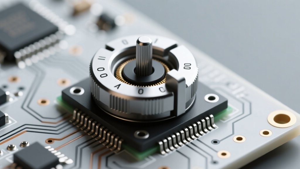

When prototyping analog circuits or designing custom control panels, searching for a generic "potentiometer picture" on a search engine will usually only yield basic 3D renders or simplified schematic symbols. While these images help with visual identification, they are virtually useless for printed circuit board (PCB) layout, panel cutout design, or predicting long-term reliability. To truly understand the component, you must look at the mechanical and electrical drawings provided in the manufacturer's datasheet.
In this datasheet breakdown, we will decode the critical visual data found in potentiometer documentation. We will use industry standards like the Bourns 3296 Series Datasheet and the Vishay P16 Panel Potentiometer Datasheet as our primary references to bridge the gap between a simple photograph and engineering reality.
The Anatomy of a Potentiometer Picture: Mechanical Outlines
The most important "potentiometer picture" you will encounter is the 2D mechanical outline. This drawing dictates how the component interacts with your physical design. For panel-mount potentiometers like the Vishay P16, the datasheet provides a top-down view of the shaft, the anti-rotation lug (keyway), and the threaded bushing. For PCB-mounted trimpots like the Bourns 3296W, the outline reveals the exact placement of the adjustment screw relative to the solder pins.
Understanding Dimensional Tolerances
A common mistake among junior designers is assuming the mechanical picture represents absolute dimensions. Datasheets always include tolerance callouts, typically ±0.5mm for standard through-hole components. If you are designing a front-panel overlay for a guitar pedal or an audio mixer, you must account for this stack-up tolerance. A 6mm shaft diameter might actually measure 5.9mm, and a 7mm panel cutout might need to be widened to 7.2mm to accommodate the bushing thread and locking washer without binding.
Decoding the Pinout and Terminal Assignments
The schematic symbol of a potentiometer is a simple resistor with an arrow pointing to the middle. However, the physical pinout picture in the datasheet reveals the spatial reality of the terminals. Standard potentiometers follow a nearly universal convention when viewed from the bottom (terminal side):
- Terminal 1 (CCW): Counter-Clockwise terminal. Connecting this to ground is standard practice for volume controls.
- Terminal 2 (Wiper): The variable output. This pin moves mechanically across the resistive track.
- Terminal 3 (CW): Clockwise terminal. Typically connected to the signal source or positive voltage.
Expert Warning: The "bottom view" mechanical picture is frequently misinterpreted during PCB footprint creation. If you mirror the footprint by accident, your CW and CCW terminals will swap, resulting in a volume knob that turns backward. Always verify the pinout picture against a physical sample with a digital multimeter (DMM) before finalizing your Gerber files.
Interpreting Taper Curves: Linear vs. Audio
Another vital visual element in the datasheet is the taper curve graph. This "picture" plots the percentage of total resistance against the percentage of shaft rotation. Selecting the wrong taper will ruin the user experience of your device.
- Linear Taper (B-Taper): The resistance changes at a constant rate. A 50% shaft rotation yields exactly 50% of the total resistance. Ideal for motor speed controls, balance pots, and sensor calibration.
- Logarithmic / Audio Taper (A-Taper): The resistance changes exponentially. At 50% rotation, you might only see 10% to 15% of the total resistance. This compensates for the logarithmic way human ears perceive loudness, making it mandatory for audio volume controls.
The DMM Verification Test
Because printed markings on potentiometer casings (like "B10k" or "A50k") can be ambiguous depending on the manufacturer's regional coding (Asian vs. European standards), you should always verify the taper curve picture with a physical test. Connect your DMM probes to Terminal 1 and Terminal 2. Rotate the shaft to the exact mechanical midpoint. If the reading is half of the total resistance, it is linear. If it is significantly lower (e.g., 1.5kΩ on a 10kΩ pot), it is an audio taper.
PCB Footprint Translation and Pad Geometry
The mechanical picture must be translated into a PCB footprint. Datasheets provide the exact pitch (distance between pins) and hole diameters. For the Bourns 3296W multi-turn trimpot, the standard pin pitch is 2.54mm (0.1 inches), but the pin width and required drill size require careful attention. The datasheet will specify a recommended drill diameter, usually 0.8mm to 1.0mm. If you use a standard 0.6mm signal via drill, the potentiometer pins will not fit, forcing you to manually enlarge the holes and risk damaging the PCB pad plating.
Comparing Common Potentiometer Series
To illustrate how datasheet specifications vary across different form factors, review the comparison table below. This data is synthesized directly from manufacturer mechanical and electrical pictures.
| Specification | Bourns 3296W (Trimpot) | Vishay P16 (Panel Mount) | Alps Alpine RK09 (Audio) |
|---|---|---|---|
| Primary Application | PCB Calibration | Industrial/HMI Panels | Audio Mixing Consoles |
| Total Resistance Tolerance | ±10% | ±20% | ±20% |
| Rotational Life (Cycles) | 1,000 (Adjustments) | 100,000 | 30,000 |
| Operating Torque | 3 to 20 gf·cm | 20 to 100 gf·cm | 10 to 60 gf·cm |
| Environmental Sealing | Open Frame | IP54 (Dust/Splash) | Open / IP40 |
Common Failure Modes Hidden in the Fine Print
A generic potentiometer picture will never show you how the component fails. For that, you must read the electrical specifications section of the datasheet, specifically looking for Contact Resistance Variation (CRV) and End Contact Resistance.
Contact Resistance Variation (CRV): This spec defines the maximum allowable noise or resistance spike generated by the wiper moving across the carbon or cermet track. In the Bourns PTV09A Datasheet, CRV is typically rated at 1% or a maximum of 2 ohms. If your circuit is a high-gain audio preamp, a wiper with degraded CRV will introduce severe scratching and popping noises.
End Contact Resistance: When the shaft is turned to the absolute minimum or maximum physical stop, the resistance between the wiper and the end terminal should ideally be zero. Datasheets usually guarantee this to be less than 1 ohm. If this value drifts higher due to oxidation or track wear, your "volume off" position might still bleed a small amount of signal, or your microcontroller's analog-to-digital converter (ADC) might never read a true 0V or 3.3V baseline.
Pro-Tip for High-Reliability Designs: If your application involves heavy vibration (e.g., automotive or aerospace), the mechanical picture of a standard open-frame carbon pot is insufficient. You must specify a conductive plastic element or a multi-turn cermet trimpot with a locking screw to prevent the wiper from shifting under mechanical shock.
Summary: Beyond the Surface Image
Ultimately, a standard "potentiometer picture" is just the starting point of your component selection process. By learning to read the mechanical outlines, decode the pinout orientations, interpret the taper curves, and analyze the hidden electrical tolerances in the datasheet, you transition from a hobbyist guessing at part placement to an engineer designing for manufacturability and long-term reliability. Always download the official PDF datasheet, verify the footprint dimensions against your CAD library, and test the physical taper before committing to a production run.