
The Anatomy of Standard Potentiometer Markings
When repairing vintage audio equipment, building custom guitar pedals, or prototyping a new microcontroller interface, selecting the correct variable resistor is critical. However, reading potentiometer markings can be incredibly confusing due to a lack of universal standardization across regions and manufacturers. Misinterpreting a single letter or digit can result in a volume knob that jumps abruptly or a bias circuit that fails to calibrate.
This comprehensive selection and buying guide will decode the cryptic stamps, printed codes, and part numbers found on potentiometers, ensuring you purchase the exact component required for your project.
Primary Resistance Values and Multiplier Codes
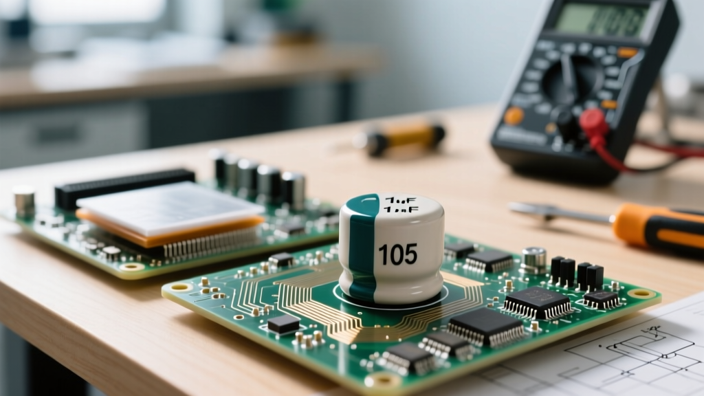
The most prominent marking on any potentiometer is its total end-to-end resistance. Modern components typically use a three-digit multiplier code, similar to surface-mount resistors. The first two digits represent the significant figures, and the third digit is the multiplier (number of zeros).
- 103 = 10 followed by 3 zeros = 10,000 Ω (10kΩ)
- 502 = 50 followed by 2 zeros = 5,000 Ω (5kΩ)
- 104 = 10 followed by 4 zeros = 100,000 Ω (100kΩ)
- 254 = 25 followed by 4 zeros = 250,000 Ω (250kΩ)
Older or larger panel-mount potentiometers may simply stamp the value directly, such as 10KΩ, 1MΩ, or 500K. When buying replacements, always verify if the circuit requires a specific resistance to maintain proper impedance matching, especially in passive audio tone stacks.
The Great Taper Trap: Regional Letter Codes
The taper (or track resistance curve) dictates how the resistance changes as you rotate the shaft. This is where the majority of buying mistakes occur. A letter is usually stamped next to the resistance value (e.g., B10K or A100K), but its meaning changes depending on the manufacturer's geographic origin.
US and Asian Standard (The Most Common)
Most modern components from brands like Bourns, ALPS, and CTS follow this convention:
- A = Audio Taper (Logarithmic). Resistance changes slowly at first, then rapidly. Essential for human-hearing volume controls.
- B = Linear Taper. Resistance changes at a constant rate. Used for panning, tone controls, and voltage dividers.
- C = Reverse Audio (Anti-Logarithmic). Used for specific fader circuits or compensation networks.
The European Vintage Standard (The Buyer's Trap)
Older European manufacturers, and some modern regional clones, flip the A and B designations. On these components:
- A = Linear Taper
- B = Audio (Logarithmic) Taper
Expert Buying Tip: Never blindly trust the letter stamp when replacing a pot in vintage European gear (like old Marshall amplifiers or certain synthesizers). Always verify the taper electrically before soldering the replacement into the PCB.
Multimeter Verification Protocol
To verify the taper of a potentiometer before installation or to confirm a faded marking:
- Solder or clip your multimeter probes to the Wiper (Pin 2) and one of the outer lugs (Pin 1 or 3).
- Rotate the shaft to the exact mechanical center (50% travel).
- Measure the resistance. If it reads exactly 50% of the total marked resistance, it is Linear (B).
- If it reads roughly 10% to 15% of the total resistance, it is an Audio/Logarithmic (A) taper.
Decoding Manufacturer-Specific Part Numbers
When buying trimmer potentiometers (trimpots) for PCB calibration, you will rarely see simple 'A' or 'B' stamps. Instead, you will encounter complex alphanumeric strings. The ubiquitous Bourns 3296 Series is the industry standard for multi-turn cermet trimpots. Let us decode a common part number: 3296W-1-103LF.
- 3296: The base series identifier (3/8" square, multi-turn).
- W: Pinout and adjustment style. 'W' means top-adjust with straight inline pins. 'P' means side-adjust, and 'X' indicates a different lead configuration.
- 1: The number of turns. '1' signifies a 25-turn precision trimpot.
- 103: The resistance code (10kΩ).
- LF: Lead-Free (RoHS compliant). If you are doing repairs on older boards, you might prefer non-LF versions for easier soldering with leaded solder, though LF is standard for new production.
Understanding these suffixes is vital. Buying a 3296P when your PCB footprint requires a 3296W will result in a component that physically cannot mount to the board.
Critical Specifications Hidden in Plain Sight
Beyond resistance and taper, advanced buyers must look for secondary markings that indicate power handling and material composition.
Wattage and Material Stamps
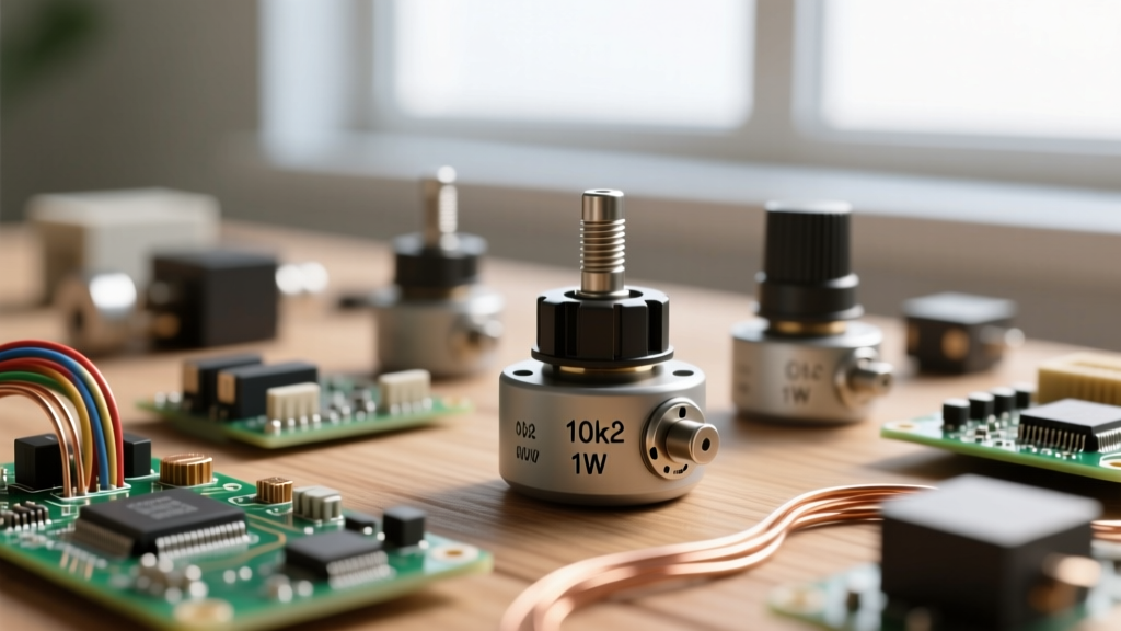
Standard carbon composition and cermet potentiometers are typically rated for 1/4W or 1/2W. If a circuit requires higher power dissipation (such as in tube amplifier bias circuits or heavy-duty motor controls), you will need a wirewound potentiometer. Wirewound models are often physically larger and may feature a stamped W (e.g., 2W) or explicit wirewound branding.
According to the Vishay P16 Cermet Potentiometer Guide, high-end cermet models offer superior stability and wattage handling compared to cheap carbon tracks, making them the preferred choice for industrial prototyping where environmental factors like humidity could degrade carbon elements.
Step-by-Step Replacement Buying Framework
When sourcing a replacement panel-mount potentiometer, follow this strict decision framework to avoid mechanical and electrical mismatches:
- Identify the Shaft Geometry: Is it a 6mm knurled split shaft (common in Stratocaster guitars and European synths), a 1/4" (6.35mm) solid round shaft (common in US guitars and amps), or a D-shaft? Buying the wrong shaft means your knobs will not fit or will slip under load.
- Measure the Shaft Length: Standard lengths vary between 15mm, 20mm, and 30mm. A shaft that is too short will not reach through the enclosure; one that is too long will leave the knob hovering awkwardly.
- Verify the Mounting Style: Check if the component uses PCB pins, solder lugs, or quick-connect spades. Solder lugs offer the most flexibility for point-to-point wiring.
- Confirm the Taper and Resistance: Use the multimeter protocol outlined above if the markings are obscured by decades of dust and oxidation.
Quick Reference: Taper and Resistance Table
Use this table as a quick cheat sheet when evaluating potentiometer markings on the workbench.
| Marking Letter | US / Asian Taper | European Taper | Typical Application |
|---|---|---|---|
| A | Audio (Logarithmic) | Linear | Volume Controls |
| B | Linear | Audio (Logarithmic) | Bias, Panning, Tone, Synth CV |
| C | Reverse Audio | Reverse Audio | Specialized Faders, Compander Circuits |
| D | Specialized Curve | Specialized Curve | Custom Audio EQ, Instrumentation |
Note: For an exhaustive list of legacy codes, the Electronics Notes Potentiometer Codes archive is an excellent secondary reference.
Common Failure Modes and When to Upgrade
When replacing a faulty component, consider why the original failed. This dictates the quality level of the replacement you should buy.
Carbon Dust and Scratchy Noise
The most common failure in cheap carbon-track potentiometers is the accumulation of carbon dust and oxidation on the wiper path, resulting in a 'scratchy' sound when rotated. If you are repairing a high-fidelity audio mixer or a premium guitar pedal, do not replace a failed carbon pot with another cheap carbon unit. Upgrade to a conductive plastic or high-grade cermet potentiometer (like the ALPS RK27 series or Vishay P16). These materials offer vastly superior wiper life, lower contact resistance, and eliminate the scratchy noise problem entirely.
Wiper Burnout and Open Circuits
If the potentiometer reads as an open circuit (infinite resistance) or shows physical melting near the center pin, it has suffered wiper burnout. This happens when the current passing through the wiper exceeds the component's wattage rating, often due to a DC offset in an audio circuit or a failed coupling capacitor. In these cases, you must either fix the upstream circuit fault or upgrade to a higher wattage wirewound or heavy-duty cermet model.
Summary
Mastering the interpretation of potentiometer markings bridges the gap between a frustrating repair experience and a seamless, professional restoration. By understanding the three-digit multiplier codes, navigating the regional taper letter traps, and decoding manufacturer-specific footprint identifiers, you can confidently source the exact variable resistor your project demands. Always keep a digital multimeter handy to verify the taper electrically, and never hesitate to upgrade the track material for mission-critical audio and prototyping applications.