
The Project: 12V Adjustable High-Power LED Dimmer
When makers first ask how to connect a potentiometer, they often assume it acts like a simple mechanical valve for electricity. In this project-based guide, we are going to dismantle that misconception by building a high-power, 12V adjustable LED work-light dimmer. By the end of this build, you will understand not just the basic pinout of a potentiometer, but how to interface low-power analog signals with high-power semiconductor switching.
We will be using a standard B10K (10,000-ohm linear) panel-mount potentiometer to control an IRLZ44N Logic-Level MOSFET, which will in turn drive a 5-Ampere, 12V LED COB strip. This project bridges the gap between basic component theory and real-world power electronics prototyping.
The Fatal Beginner Mistake: Series vs. Signal Wiring
Before we touch a single wire, we must address the most common failure mode in beginner prototyping: wiring a potentiometer in series with a high-power load.
A typical breadboard or panel-mount B10K potentiometer is rated for 0.5 Watts of power dissipation. If you wire this component in series with a 12V LED strip drawing 5 Amps, and turn the knob to allow full current flow, the internal carbon track will attempt to dissipate massive amounts of heat. The result? The potentiometer will literally melt, smoke, or catch fire.
Engineering Rule of Thumb: Never use a standard potentiometer as a direct current-limiting resistor for loads exceeding a few milliamps. Instead, use the potentiometer as a voltage divider to generate a control signal, and use a transistor or MOSFET to handle the heavy current.
Anatomy of a B10K Potentiometer: Pinout and Wiper Mechanics
To understand how to connect a potentiometer correctly, you must visualize its internal mechanics. According to All About Circuits, a potentiometer consists of a resistive element (usually a carbon composition or cermet track) and a movable contact called a wiper.
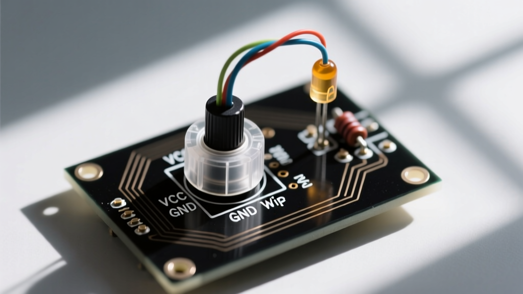
- Pin 1 (CCW Terminal): Connected to one end of the resistive track. In our circuit, this will tie to Ground (0V).
- Pin 3 (CW Terminal): Connected to the opposite end of the track. This will tie to our 12V supply.
- Pin 2 (The Wiper): The middle pin. As you rotate the shaft (typically through a 270° to 300° mechanical arc), the wiper slides along the carbon track, tapping off a variable voltage between 0V and 12V.
The 'B' in B10K denotes a Linear Taper, meaning the resistance changes at a constant rate relative to the shaft angle. If you rotate the knob 50%, the wiper outputs exactly 50% of the input voltage (6V).
Component Selection: Why the IRLZ44N MOSFET?
Why not use a standard NPN transistor like the 2N2222? The 2N2222 maxes out around 800mA and requires continuous base current to stay on, which wastes power and alters our voltage divider ratio.
The IRLZ44N is an N-Channel Logic-Level MOSFET. It has two critical advantages for this project:
- High Current Capacity: It can handle up to 47 Amps continuously (with proper heatsinking), easily covering our 5A LED strip.
- Low Gate Threshold (Vgs): It fully turns on with a gate voltage as low as 4V to 5V, making it highly responsive to the 0-12V sweep provided by our B10K potentiometer.
Step-by-Step: How to Connect a Potentiometer to a MOSFET
Now we move to the workbench. Follow this exact wiring topology to ensure stable dimming without oscillation or thermal runaway.
Step 1: Wire the Voltage Divider
Connect Pin 1 of the B10K potentiometer to your power supply Ground. Connect Pin 3 to the 12V positive rail. At this point, if you probe Pin 2 (the wiper) with a multimeter, you should see the voltage smoothly sweep from 0.00V to 12.00V as you turn the shaft.
Step 2: Implement Gate Protection (Crucial)
MOSFET gates act like tiny capacitors. If you connect the wiper directly to the gate, you risk two issues: high-frequency ringing and floating-gate turn-on. We must add two resistors:
- 100Ω Gate Stopper Resistor: Wire this in series between the potentiometer wiper (Pin 2) and the MOSFET Gate. This dampens parasitic inductance and prevents high-frequency oscillation that can destroy the MOSFET.
- 10kΩ Pull-Down Resistor: Wire this between the MOSFET Gate and Ground. As noted in SparkFun's tutorial on voltage dividers and analog signals, mechanical wipers can suffer from 'contact bounce' or momentary open circuits. If the wiper loses contact, the gate becomes 'floating' and can pick up ambient electromagnetic interference (EMI), randomly turning your LEDs on at full blast. The 10kΩ resistor safely bleeds this charge to ground.
Step 3: Wire the Load
Connect the MOSFET Source pin directly to Ground. Connect the MOSFET Drain pin to the negative terminal of your 12V LED strip. Finally, connect the positive terminal of the LED strip to the 12V positive rail.
Real-World Failure Modes and Multimeter Troubleshooting
Even with a perfect schematic, physical prototyping introduces variables. Here is how to troubleshoot the most common anomalies when building this circuit.
Anomaly 1: The LEDs Flicker at Low Dimming Levels
The Cause: The MOSFET is operating in its linear (ohmic) region rather than fully saturating. At low gate voltages (e.g., 2V), the IRLZ44N is barely conducting, acting as a variable resistor. This causes the MOSFET to dissipate significant heat and become susceptible to thermal noise.
The Fix: Ensure your MOSFET has a small heatsink attached. For purely analog dimming, some flicker at the bottom 10% of the pot's rotation is normal due to the gate threshold voltage (Vgs(th)) of the silicon.
Anomaly 2: The Potentiometer Feels 'Scratchy' or Erratic
The Cause: Wiper noise. If you are using an older or cheap carbon-track potentiometer, dust or oxidation on the track causes momentary resistance spikes.
The Fix: For analog LED dimming, the human eye's persistence of vision usually masks this. However, if you are adapting this circuit for audio volume control, you must spray the pot with a specialized contact cleaner (like DeoxIT) or upgrade to a cermet or conductive plastic potentiometer (e.g., Bourns 3590 series) which offers vastly superior wiper stability.
Calibrating the Taper: Linear vs. Audio (Logarithmic)
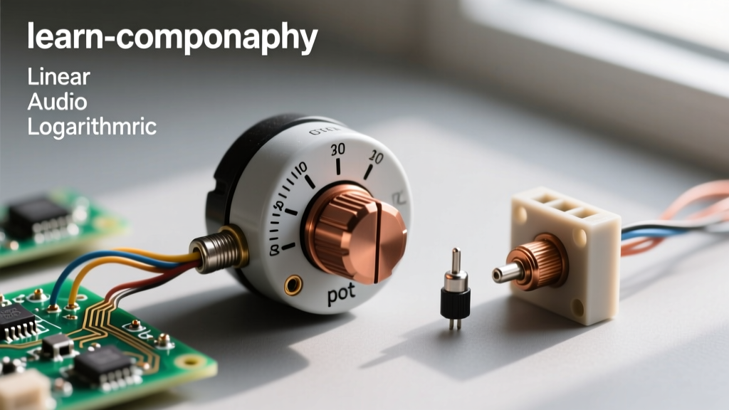
Understanding component tapers is vital for user experience. Below is a decision matrix for selecting the correct potentiometer taper based on your specific project application.
| Taper Type | Marking Prefix | Resistance Curve | Best Application |
|---|---|---|---|
| Linear | B (e.g., B10K) | Straight line (50% rotation = 50% resistance) | Voltage dividers, motor speed control, sensor calibration, LED dimming. |
| Audio (Logarithmic) | A (e.g., A10K) | Exponential curve (mimics human hearing perception) | Audio amplifiers, volume knobs, tone controls. |
| Reverse Log | C (e.g., C10K) | Inverse exponential curve | Specific cross-fader audio applications, specialized instrument controls. |
Prototyping Tips: Soldering Panel Mount vs. PCB Pots
When transitioning from a breadboard to a soldered perfboard or custom PCB, the physical form factor of your potentiometer dictates your assembly strategy.
Panel Mount Pots (e.g., Alpha RD901F): These feature heavy-duty lugs and a threaded bushing for mounting to an enclosure. When soldering thick 18AWG silicone wires to the lugs, tin the wires and the lugs separately first. Use a 40W to 60W soldering iron; a standard 15W precision iron will not transfer enough heat to the massive brass lug, resulting in a cold, brittle solder joint that will crack under mechanical stress when the user turns the knob.
PCB Mount Pots (e.g., Bourns 3386 Trimpots): These are designed to be soldered directly to a circuit board. They are excellent for 'set-and-forget' calibration inside a project box. However, they are not rated for continuous daily mechanical cycling. If your end-user will be adjusting the dimmer daily, always use a panel-mount pot wired to the PCB via a JST connector or stranded wire.
Final Power-On and Validation
Before applying 12V to the LED strip, use your multimeter to verify the gate voltage. Turn the potentiometer fully counter-clockwise; the gate should read 0.00V (held low by the 10kΩ pull-down). Slowly rotate the shaft clockwise. You should see the gate voltage rise smoothly. Once it crosses approximately 3.5V to 4.0V, the IRLZ44N will begin to conduct, and your LED strip will smoothly fade from pitch black to blindingly bright.
Mastering how to connect a potentiometer in this signal-to-power topology is a foundational skill in electronics. You have successfully isolated your fragile analog control circuit from your high-current load, ensuring a robust, fire-safe, and highly responsive dimmer that will survive years of daily use.