
Defining the Divide: What Is a Conductor and Insulator?
At the most fundamental level of electrical engineering and DIY electronics, understanding what is conductor and insulator material requires looking past the physical wire and into the quantum behavior of electrons. Whether you are sizing a 200-amp residential service or soldering a microscopic SMD component, the flow of current relies entirely on the atomic structure of the materials you choose.
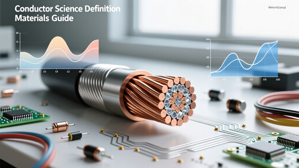
A conductor is a material that permits the free flow of electrical charge (electrons) with minimal resistance. An insulator, conversely, tightly binds its electrons, resisting current flow and forcing electricity to stay within the intended conductive path. But why do some materials conduct while others block? The answer lies in solid-state physics and energy band theory.
The Physics: Energy Bands and Electron Mobility
To truly grasp material behavior, we must look at the band theory of solids. Electrons in a solid occupy specific energy levels, which merge into continuous bands.
Conductors: Overlapping Valence and Conduction Bands
In conductive metals like copper and silver, the valence band (the highest energy band containing electrons at absolute zero) and the conduction band (the next available empty band) overlap. Because there is zero band gap (0 eV), electrons require virtually no external energy to jump into the conduction band and move freely through the atomic lattice when a voltage is applied.
Insulators: The Wide Band Gap Barrier
Insulators possess a massive energy barrier—known as the band gap—between the valence and conduction bands. For materials like PTFE (Teflon) or glass, this gap is typically greater than 4 to 8 electron volts (eV). At standard operating voltages and temperatures, thermal energy is vastly insufficient to excite electrons across this gap, resulting in effectively zero current flow.
Comprehensive Conductor and Insulator Reference Chart
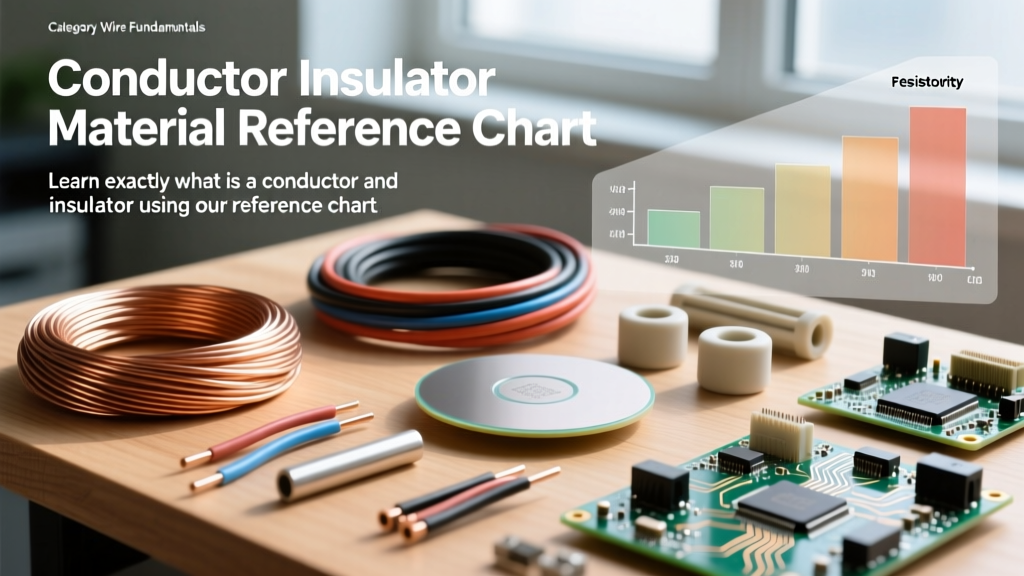
The following reference chart contrasts the fundamental electrical properties of common materials used in wiring, PCB design, and high-voltage transmission.
| Material | Category | Resistivity (Ω·m @ 20°C) | Band Gap (eV) | Primary Electrical Application |
|---|---|---|---|---|
| Silver | Conductor | 1.59 × 10⁻⁸ | 0 (Overlapping) | High-end audio contacts, RF shielding |
| Copper (ETP) | Conductor | 1.68 × 10⁻⁸ | 0 (Overlapping) | Branch circuit wiring, PCB traces, busbars |
| Aluminum (1350) | Conductor | 2.65 × 10⁻⁸ | 0 (Overlapping) | Overhead transmission, service entrances |
| Silicon | Semiconductor | 2.3 × 10³ | 1.11 | Microcontrollers, solid-state relays |
| Glass (Borosilicate) | Insulator | ~1.0 × 10¹² | ~4.0 - 9.0 | High-voltage standoff insulators, fuses |
| PTFE (Teflon) | Insulator | >1.0 × 10¹⁸ | ~8.0 | Aerospace wiring, high-temp solder sleeves |
| XLPE | Insulator | >1.0 × 10¹⁶ | ~8.5 | Underground medium-voltage distribution |
Evaluating Conductors for Wire Sizing and DIY Projects
When selecting a conductor, resistivity is only part of the equation. Mechanical strength, thermal expansion, and oxidation resistance dictate real-world performance.
Copper: The Undisputed Standard
Electrolytic Tough Pitch (ETP) copper is the baseline for almost all residential and commercial wiring. It offers an excellent balance of high conductivity, tensile strength, and solderability. However, for high-end audio or precision measurement equipment, Oxygen-Free Copper (OFC) is preferred to prevent hydrogen embrittlement and minimize skin-effect losses at high frequencies.
Aluminum: The Lightweight Alternative
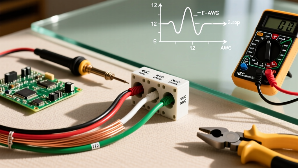
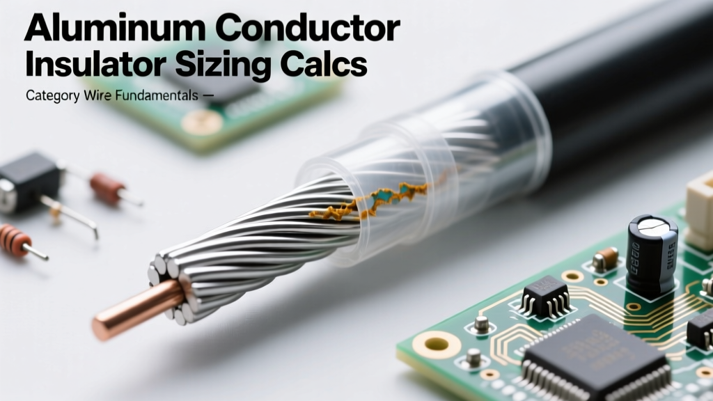
Aluminum is roughly 61% as conductive as copper by volume, but it is significantly lighter and cheaper. This makes it the undisputed king of overhead utility transmission lines. However, in residential DIY projects, pure aluminum wire is a known fire hazard due to mechanical creep (deformation under screw pressure) and galvanic corrosion when mated with copper or brass terminals. Modern electrical codes mandate the use of Copper Development Association approved AA-8000 series aluminum alloys, paired with CO/ALR rated receptacles, to mitigate these failure modes.
Selecting the Right Insulator for Environmental Stress
Insulators do more than just prevent short circuits; they provide mechanical support, resist chemical degradation, and manage thermal loads. According to NFPA 70 (National Electrical Code) Article 310, insulation types are strictly categorized by temperature rating and environmental exposure.
Thermoplastics vs. Thermosets
- PVC (Polyvinyl Chloride): The most common thermoplastic insulation (found in standard THHN wire). It is flexible, cheap, and rated for 90°C in dry locations. However, PVC softens under high heat and releases highly toxic, corrosive hydrogen chloride (HCl) gas when burned, making it unsuitable for confined plenums or marine engine bays.
- XLPE (Cross-Linked Polyethylene): A thermoset material created by irradiating or chemically treating PE to form a 3D molecular lattice. XLPE will not melt under extreme heat. It boasts a 250°C short-circuit rating compared to PVC's 150°C, making it mandatory for high-capacity underground feeder cables.
- PTFE (Polytetrafluoroethylene / Teflon): Offering the lowest dielectric constant (2.1) and extreme temperature resistance (up to 260°C), PTFE is the gold standard for aerospace and high-frequency RF coaxial cables. Its primary weakness is cold flow—it deforms permanently under sustained mechanical pressure, requiring specialized ferrule crimps rather than standard screw terminals.
Real-World Failure Modes: When Insulators Become Conductors
No insulator is perfect. When subjected to extreme electrical, thermal, or environmental stress, insulating materials can catastrophically fail and begin to conduct.
Dielectric Breakdown
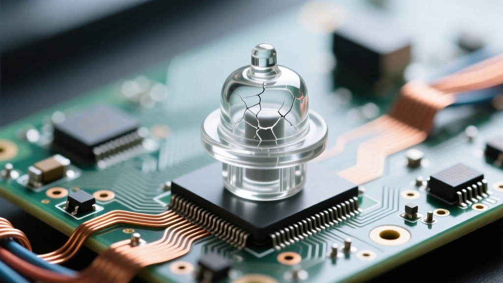
Every insulator has a dielectric strength, measured in kilovolts per millimeter (kV/mm). If the applied electric field exceeds this threshold, electrons are violently ripped from their atoms, creating a conductive plasma channel. In solid wire insulation, this results in a permanent, carbonized puncture path that will continuously arc.
Water Treeing and Tracking
In underground medium-voltage cables, microscopic impurities combined with moisture and alternating current fields cause water trees to grow within the XLPE insulation. Over years, these dendritic moisture channels bridge the gap between the conductor and the ground shield, leading to a catastrophic short circuit. Similarly, surface contamination (dust, salt) on standoff insulators can absorb moisture, creating a conductive path known as carbon tracking that eventually burns a permanent groove into the material.
Expert Troubleshooting Tip: If you are diagnosing intermittent ground faults in an older DIY control panel, do not rely solely on a standard digital multimeter. Use a Megohmmeter (Megger) to apply 500V or 1000V DC to the circuit. Standard meters use less than 3V, which will not reveal microscopic insulation breakdown or moisture ingress that only manifests under peak operating voltages.
Summary: Engineering the Perfect Path
Understanding what is conductor and insulator material at a quantum and practical level is the foundation of all safe electrical design. Conductors like ETP copper provide the low-resistance highway for electrons, while advanced insulators like XLPE and PTFE act as the impenetrable guardrails. By matching the resistivity, band gap, and thermal limits of these materials to your specific voltage and environmental requirements, you ensure both the efficiency and the safety of your electrical systems.