
The Core Concept: What Exactly is One Phase Electricity?
If you live in a standard residential home in North America, every time you flip a light switch or plug in your phone charger, you are utilizing one phase electricity. Often referred to in technical manuals as single-phase power, this electrical distribution method is the undisputed backbone of residential and light-commercial wiring. But what does 'one phase' actually mean, and how does it safely deliver power to your outlets?
At its core, one phase electricity refers to an Alternating Current (AC) system where all voltage and current waveforms peak and valley at the exact same time. If you were to hook up an oscilloscope to a standard residential circuit, you would see a single, continuous sine wave oscillating at 60 Hertz (60 complete cycles per second). Unlike three-phase power—where three separate sine waves are offset by 120 degrees to provide a constant, uninterrupted flow of power to heavy industrial motors—one phase electricity pulses. The voltage hits a positive peak, drops through zero to a negative peak, and returns to zero, 60 times every second.
According to Fluke Corporation's electrical testing guidelines, understanding this single sine wave is critical for DIYers and apprentice electricians, as it dictates how we size wires, select breakers, and troubleshoot voltage drops in residential environments.
The Split-Phase Transformer Trick: How 120V Becomes 240V
One of the most common points of confusion for beginners is the concept of 'split-phase' power. If one phase electricity only provides a single sine wave, how do heavy appliances like electric dryers, ovens, and HVAC compressors get the 240 volts they require to operate?
The secret lies at the utility pole (or the green pad-mounted transformer in your yard). The utility company delivers a single phase of high-voltage electricity to the primary coil of the transformer. However, the secondary coil—which feeds your home's main service panel—is center-tapped. This center tap is connected directly to the earth (ground) and becomes your Neutral wire.
Because the secondary winding is split perfectly in half, it creates two opposing 120V legs (often called L1 and L2). Here is how the math and physics work out in your breaker panel:
- Leg 1 to Neutral: 120 Volts (Used for standard lighting and receptacles)
- Leg 2 to Neutral: 120 Volts (Used for standard lighting and receptacles)
- Leg 1 to Leg 2: 240 Volts (Used for high-wattage appliances)
It is vital to understand that this is not two-phase electricity. It is still fundamentally one phase electricity, just cleverly divided by a center-tapped transformer to give homes the versatility of both 120V and 240V power from a single utility feed.
Anatomy of a One Phase Branch Circuit
When wiring a standard 120V branch circuit under the rules of the National Electrical Code (NFPA 70), you will work with three distinct conductors. Misidentifying these is a leading cause of residential electrical fires and shock hazards.
1. The Hot (Ungrounded) Conductor
Typically insulated in Black or Red, this wire carries the 120V sine wave from the breaker to your load (like a TV or lamp). It is the active, dangerous wire that will deliver a severe shock if touched while the circuit is energized.
2. The Neutral (Grounded) Conductor
Insulated in White or Gray, the neutral completes the circuit. Beginner Warning: Many DIYers mistakenly believe the neutral wire is safe to touch because it is 'grounded' at the panel. In a one phase circuit, the neutral is a current-carrying conductor. It carries the exact same amperage back to the panel as the hot wire. If a neutral connection becomes loose or disconnected while a load is running, the neutral wire upstream of the break will become fully energized at 120V.
3. The Equipment Grounding Conductor (EGC)
Bare copper or Green insulated, this wire carries zero current during normal operation. Its sole purpose is to provide a low-resistance path back to the panel to trip the breaker in the event of a short circuit or ground fault.
Expert Subpanel Tip: In a main service panel, the Neutral and Ground bars are bonded together. However, if you are extending one phase electricity to a detached garage or subpanel, NEC Article 250.32 strictly requires you to separate the neutral and ground bars. Bonding them in a subpanel causes normal neutral return current to flow through the bare ground wires, creating a severe shock hazard and potential electromagnetic interference.
Wire Sizing and Breaker Matching for Single-Phase Loads
Sizing wire for one phase electricity requires consulting NEC Table 310.16, which dictates the ampacity (current-carrying capacity) of copper and aluminum conductors. A common mistake beginners make is reading the 90°C column of the table. Because most standard residential breakers and receptacles are rated for 60°C or 75°C termination limits, you must size your wire based on the lowest temperature rating of any component in the circuit.
Below is a practical reference chart for standard residential one-phase copper wiring (NM-B / Romex):
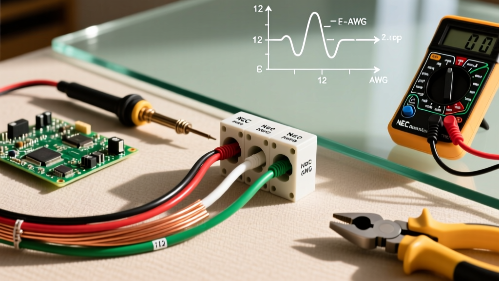
| Wire Gauge (AWG) | Max Breaker Size | Typical One-Phase Application | NEC Reference Rule |
|---|---|---|---|
| 14 AWG | 15 Amps | General lighting, bedroom outlets | NEC 240.4(D) Small Conductor Rule |
| 12 AWG | 20 Amps | Kitchen countertop receptacles, bathroom GFCI | NEC 210.11 Branch Circuit Requirements |
| 10 AWG | 30 Amps | 120V RV receptacles, heavy-duty window AC units | NEC 310.16 Ampacity Tables |
| 8 AWG | 40 Amps | 240V Electric baseboard heaters, EV chargers | NEC 240.4(B) Overcurrent Device Sizing |
| 6 AWG | 50 Amps | 240V Electric ranges, heavy welders | NEC 250.122 Equipment Ground Sizing |
Voltage Drop: The Silent Threat to One Phase Motors
When routing one phase electricity over long distances—such as powering a well pump at the end of a 200-foot driveway or a dust collector in a large woodworking shop—wire sizing for ampacity is only half the battle. You must also calculate voltage drop.
Copper wire has inherent resistance. As current flows through a long, undersized wire, voltage is lost as heat before it reaches the load. The NEC recommends (in Informational Note to Section 210.19) that branch circuit voltage drop should not exceed 3%. For a 120V circuit, a 3% drop means you can only afford to lose 3.6 Volts. For a 240V circuit, the limit is 7.2 Volts.
Why does this matter? Inductive loads like air compressors and well pumps are highly sensitive to voltage sag. If a motor rated for 240V only receives 220V due to wire resistance, it will draw significantly higher amperage to compensate for the missing wattage (Watts = Volts x Amps). This excess amperage generates severe heat inside the motor windings, leading to premature insulation failure and burned-out motors. Always use a voltage drop calculator and upsize your wire (e.g., moving from 10 AWG to 8 AWG) for runs exceeding 75 feet on 15A or 20A circuits.
When One Phase Electricity Isn't Enough: The Three-Phase Threshold
While one phase electricity is perfect for heating elements, lighting, and small fractional-horsepower motors, it hits a hard limit in heavy manufacturing and large commercial spaces. Because the single sine wave drops to zero volts 120 times a second, large single-phase motors require heavy start capacitors and centrifugal switches to 'push' the rotor past the zero-voltage dead spots.
If you are setting up a home machine shop with industrial lathes, CNC routers, or 5+ HP air compressors, you will likely need to upgrade to three-phase power, or install a rotary phase converter or Variable Frequency Drive (VFD). Three-phase power delivers a constant, never-dropping stream of torque, allowing motors to run cooler, smaller, and vastly more efficiently. However, for 99% of residential DIY projects, appliance installations, and standard wiring repairs, mastering the fundamentals of split-phase, one phase electricity is the most valuable skill you can develop.