
The Critical Role of CAT III in Distribution Troubleshooting
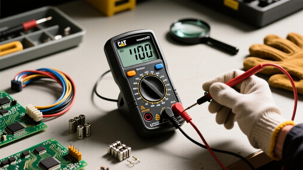
When troubleshooting fixed wiring, distribution panels, and heavy industrial appliances, a standard electronics multimeter is not just inadequate—it is a lethal liability. The International Electrotechnical Commission (IEC) 61010-1 standard defines CAT III as the distribution level. This encompasses three-phase distribution, single-phase commercial lighting, fixed non-portable loads, and bus bars in manufacturing plants.
A true CAT III multimeter is engineered to withstand transient overvoltages that routinely occur when heavy inductive loads (like large motors or transformer banks) switch on and off. For a 600V CAT III rated meter, the internal components and air gaps must survive a 6kV impulse transient with a 2-ohm source impedance. If you are troubleshooting a 480V motor control center (MCC) or a commercial breaker panel using a CAT II meter, an invisible voltage spike can arc across the meter's internal PCB, causing catastrophic failure and severe injury.
This guide serves as a comprehensive troubleshooting manual. We will cover how to diagnose erratic readings in the field, resolve phantom voltages, and troubleshoot the CAT III multimeter itself when hardware failures occur.
Diagnostic Matrix: CAT III Multimeter Error Codes & Hardware Failures
Before assuming a circuit is faulty, you must verify the integrity of your testing equipment. Industrial environments are harsh, and multimeters take a beating. Use this diagnostic matrix to troubleshoot your CAT III meter.
| Symptom / Error | Probable Cause | Troubleshooting Step |
|---|---|---|
| Display shows 'OL' on Resistance/Continuity | Blown internal mA/uA fuse or damaged test lead wire. | Perform a lead continuity test. If leads are good, open the battery door and check the glass/ceramic fuses with a secondary meter. |
| Erratic AC Voltage Readings (Fluctuating wildly) | Phantom (ghost) voltage from capacitive coupling in adjacent cable trays. | Switch the meter to Low-Impedance (LoZ) mode to bleed off capacitive charge, or apply a physical load to the circuit. |
| Display Blank or 'Low Battery' despite new batteries | Corroded battery contacts or blown main High Breaking Capacity (HBC) fuse. | Clean contacts with isopropyl alcohol. If the issue persists, the 11A/1000V HBC fuse may have sacrificed itself during a previous overload. |
| Continuity Beep is Delayed or Silent | Internal piezo buzzer failure or firmware glitch. | Reset the meter by removing batteries for 60 seconds. Test continuity on a known short circuit to verify threshold response. |
Field Troubleshooting: Solving Phantom Voltages and Floating Grounds
One of the most common issues electricians face when troubleshooting CAT III environments—such as long cable runs in commercial cable trays or multi-gang switch boxes—is phantom voltage. This occurs when de-energized wires run parallel to energized wires for extended distances, creating a capacitor that induces a 'ghost' AC voltage on the dead wire.
A high-impedance CAT III multimeter (typically 10 Megohms input impedance) will read this induced voltage as a real, dangerous potential, sometimes showing 60V to 110V on a completely dead circuit. This leads to misdiagnosis and unnecessary downtime.
The Low-Impedance (LoZ) Solution
To troubleshoot this effectively, modern CAT III multimeters like the Fluke 117 or Klein Tools MM700 feature a LoZ (Low Impedance) mode. When engaged, the meter drops its internal input impedance from 10 Megohms down to approximately 3 kilohms.
- Step 1: Measure the suspect circuit in standard AC Voltage mode. Note the erratic or unexpected voltage.
- Step 2: Switch to LoZ mode. The low impedance acts as a bleed resistor, safely dissipating the capacitively coupled phantom energy.
- Step 3: If the voltage drops to near zero (e.g., 0.5V), the circuit is de-energized and safe to work on. If the voltage remains stable, it is a true hard-wired voltage source.
Note: Never use LoZ mode in circuits where the low impedance could inadvertently trip a breaker or damage sensitive electronic control boards.
Troubleshooting Motor Control Centers (MCCs) Safely
Motor Control Centers represent the heart of CAT III environments. Troubleshooting a 480V 3-phase motor starter requires strict adherence to CAT III protocols. When a motor fails to start, the initial instinct is to probe the contactor output.
However, troubleshooting an MCC requires checking for voltage unbalance and harmonic distortion. A standard CAT III multimeter can measure RMS voltage, but if the facility uses Variable Frequency Drives (VFDs), the PWM (Pulse Width Modulation) waveform can confuse standard averaging meters. When troubleshooting VFD output to a motor, you must ensure your CAT III meter has a dedicated VFD Low-Pass Filter mode (found on advanced models like the Fluke 87V). Without this filter, the high-frequency carrier wave of the VFD will cause the meter's AC voltage readings to be highly inaccurate, leading technicians to falsely diagnose a motor winding failure.
Why Your CAT III Multimeter Keeps Blowing Fuses (And How to Stop It)
The most frequent hardware troubleshooting issue submitted to tool manufacturers is the 'blown fuse' scenario. This almost always happens when a technician forgets to move the red test lead from the 'Amps' (A) jack back to the 'Voltage/Ohms' (VΩ) jack, and then places the probes across a 480V CAT III bus bar.
Because the Amps jack utilizes an internal shunt with near-zero resistance, placing it across a voltage source creates a dead short. In a CAT III environment, the available fault current can exceed 10,000 amps instantly.
The High Breaking Capacity (HBC) Mandate
If your meter frequently suffers catastrophic failure or the fuse glass shatters inside the housing, you are using the wrong replacement fuses. A true CAT III multimeter requires High Breaking Capacity (HBC) ceramic, sand-filled fuses.
For example, the Fluke 87V requires an 11A/1000V HBC fuse (Fluke part #803293). The special quartz sand inside the ceramic tube absorbs the explosive energy of the arc, quenching the plasma before it can breach the meter housing. Never replace an HBC fuse with a standard glass electronics fuse. A glass fuse will vaporize instantly under a CAT III transient, sustaining an arc plasma that will melt the multimeter and cause severe burns to the user.
OSHA & NFPA 70E Safety Warning: Before opening any CAT III panel for troubleshooting, always perform a Live-Dead-Live test. Verify your meter on a known live source, test the target circuit, and immediately re-verify the meter on the known live source to ensure the meter did not fail during the test.
Verifying CAT III Integrity: Probe and Insulation Inspections
Troubleshooting your methodology is just as important as troubleshooting the meter. CAT III ratings apply to the entire testing system, not just the multimeter body. If you are using a CAT III rated Fluke 117 but have attached cheap, unrated replacement test leads from an online marketplace, your entire setup is downgraded to the lowest common denominator.
Inspect your test leads for the following failure modes:
- Cracked Insulation: Flex the silicone leads near the probe tip. Micro-fractures can allow moisture ingress, drastically reducing the dielectric breakdown voltage.
- Missing Finger Guards: CAT III probes require physical finger guards to prevent slippage onto live bus bars. If the guard is loose or missing, discard the lead.
- Worn Tips: Blunt or hooked tips can slip off screw terminals inside deep contactor blocks, causing phase-to-phase shorts. Replace with sharp, replaceable probe tips designed for industrial panels.
Authoritative References & Standards
To maintain compliance and ensure safety during electrical troubleshooting, always refer to the latest safety standards regarding measurement categories and personal protective equipment (PPE).
- Fluke: Understanding Multimeter Safety Ratings - Detailed breakdown of IEC 61010-1 CAT III and CAT IV transient impulse testing.
- OSHA Electrical Safety Guidelines - Federal regulations regarding lockout/tagout and testing protocols in industrial environments.
- NFPA 70E Standard for Electrical Safety in the Workplace - The benchmark for establishing arc flash boundaries and selecting CAT-rated test equipment.