
The Procurement Dilemma: Why Polarity Dictates Your LED Purchase
When sourcing light-emitting diodes for a new PCB design or a breadboard prototype, most buyers focus on forward voltage, luminous intensity (mcd), and emission wavelength. However, overlooking the fundamental physics of the LED cathode and anode is a primary cause of assembly delays, blown components, and wasted procurement budgets. Unlike incandescent bulbs, LEDs are diodes; they possess a strict PN junction that only permits current flow in one direction. Purchasing the wrong polarity configuration—especially in multi-emitter packages like RGBs—or failing to verify physical polarity markers before automated SMT placement can result in catastrophic reverse-bias failures.
This comprehensive buyer's guide moves beyond basic theory. We will dissect how to identify the LED cathode and anode across various commercial packages, evaluate common-anode versus common-cathode architectures for microcontroller integration, and recommend the precise testing equipment required to validate your inventory upon delivery.
Decoding Physical Markers Across LED Packages
Manufacturers use distinct visual and physical cues to denote polarity, but these markers vary wildly depending on the form factor. Relying on a single identification method is a common procurement mistake that leads to soldering errors on the assembly line.
Through-Hole (THT) LEDs: Legs, Flats, and Internal Flags
For standard 3mm, 5mm, and 10mm through-hole LEDs, the industry standard dictates that the longer lead is the anode (positive) and the shorter lead is the cathode (negative). However, never base your circuit design solely on lead length. If you are purchasing from surplus bins, or if the supplier pre-clips leads for automated insertion, this metric is useless.
Instead, inspect the epoxy lens and the internal structure. According to the Components101 5mm LED Datasheet Guide, the cathode side of the THT LED housing will feature a flattened edge on the otherwise circular plastic flange. Furthermore, looking inside the clear or diffused epoxy dome reveals the 'anvil' and the 'post'. The larger, flag-like internal structure (the anvil) is the cathode, while the smaller post is the anode. Note that a small subset of specialty LEDs reverses this internal flag rule, making multimeter verification mandatory for high-volume purchases.
Surface Mount (SMD) LEDs: Silkscreens and Heat Sinks
SMD LEDs (such as 0603, 0805, and 1206 imperial sizes) eliminate lead lengths entirely, forcing buyers to rely on microscopic visual indicators. When reviewing supplier tape-and-reel packaging or designing your PCB footprint, look for the following anode/cathode identifiers:
- The Green Dot or Line: Many SMD LEDs feature a tiny green dot or a silkscreen line on the top surface, which universally denotes the cathode.
- The T-Shaped Pad: On the bottom of the component, the cathode pad is often wider or features a T-shaped thermal relief pattern compared to the anode pad.
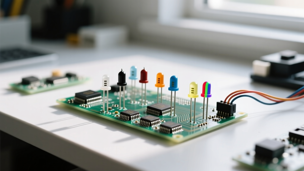
- The Notched Corner: For larger packages like the 5050 or PLCC-4 (common in RGB LEDs), a chamfered or notched corner on the plastic housing points directly to the cathode or pin 1.
When designing your PCB silkscreen, always mirror these manufacturer markings. A mismatched footprint silkscreen is a leading cause of reversed polarity during manual rework.
Common Anode vs. Common Cathode: The RGB Buying Decision
When purchasing multi-color RGB LEDs, the polarity architecture fundamentally changes your Bill of Materials (BOM) and driver circuitry. You must choose between Common Anode (CA) and Common Cathode (CC) configurations.
In a Common Cathode RGB LED (like the Cree CLVBA-FKA), the three internal diodes share a single ground connection. You switch the anodes using high-side drivers or microcontroller pins. Conversely, a Common Anode RGB LED shares a single VCC connection, requiring you to sink current through the cathodes using low-side N-channel MOSFETs or microcontroller GPIO pins.
Expert Procurement Tip: Most standard microcontrollers (including AVR and ESP32 architectures) are vastly superior at sinking current (pulling to ground) than sourcing current. Therefore, purchasing Common Anode RGB LEDs allows you to utilize simpler, cheaper, and more efficient low-side N-channel MOSFETs (like the 2N7000 or BSS138) for PWM dimming, avoiding the need for costly P-channel MOSFETs or high-side driver ICs required by Common Cathode setups.
For addressable LEDs (such as the WS2812B or SK6812), the polarity debate is moot for the light emission itself, as the internal driver IC handles the PN junction biasing. However, you must still strictly observe the DIN/DOUT and VCC/GND polarity markers to prevent instant destruction of the internal CMOS logic.
Buyer’s Matrix: Matching LED Types to Circuit Requirements
| LED Package Type | Primary Cathode Identifier | Primary Anode Identifier | Best Procurement Use Case |
|---|---|---|---|
| 5mm THT Standard | Flat lens edge / Short lead | Long lead / Internal post | Breadboarding, panel indicators, hobbyist kits |
| 0805 / 1206 SMD | Green dot / Silkscreen line | Clear side / Untouched pad | High-density PCBs, automated SMT pick-and-place |
| PLCC-4 RGB (CC) | Pins 1, 3, 4 (R, G, B Anodes) | Pin 2 (Common Cathode) | High-side switching, P-channel MOSFET arrays |
| PLCC-4 RGB (CA) | Pin 2 (Common Anode / VCC) | Pins 1, 3, 4 (R, G, B Cathodes) | Low-side N-channel MOSFETs, direct MCU sinking |
| Automotive 12V Module | Black wire / '-' stamp | Red wire / '+' stamp | 12V systems, includes internal reverse protection |
Essential Testing Tools to Verify Polarity Before Soldering
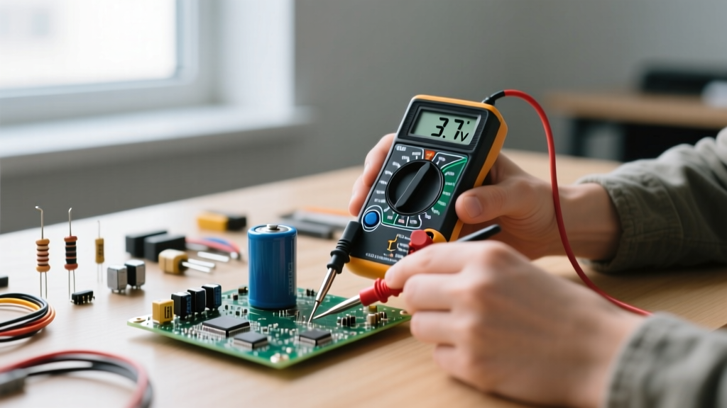
Do not trust the supplier's tape-and-reel orientation blindly. Verifying the LED cathode and anode upon delivery requires the right testing equipment. A standard continuity tester on a cheap multimeter will not suffice, as it does not provide enough forward voltage ($V_F$) to illuminate the diode, leaving you guessing based on arbitrary resistance readings.
For professional verification, invest in a multimeter with a dedicated Diode Test Mode that outputs at least 3.0V. The SparkFun LED Tutorial highlights that modern blue and white LEDs possess a forward voltage drop of roughly 2.8V to 3.3V. If your multimeter only outputs 1.5V in diode mode, it will read as an 'Open Circuit' (OL), leading you to falsely conclude that a batch of perfectly good white LEDs is dead stock. The Fluke 117 True-RMS multimeter, for example, features a specialized LED test position that safely sources enough voltage to illuminate high-$V_F$ diodes without exceeding their maximum continuous forward current, instantly confirming both functionality and polarity.
Avoiding Catastrophic Reverse-Bias Failures
Understanding the LED cathode and anode is ultimately about preventing reverse-bias breakdown. Standard indicator LEDs have a maximum reverse voltage rating ($V_R$) of just 5V. If you accidentally wire a 5mm LED in reverse across a 12V rail, the PN junction will experience avalanche breakdown, permanently destroying the crystal lattice and turning the LED into a dead short or an open circuit.
If your project involves high-voltage environments, automotive applications, or inductive kickback scenarios, alter your purchasing strategy. Buy LEDs that feature integrated reverse-protection diodes or purchase external Schottky diodes (like the BAT54) to place in parallel or series. While this increases the BOM cost by fractions of a cent per unit, it eliminates the risk of field failures caused by accidental polarity reversal during end-user installation.
Final Procurement Checklist for Engineers and Hobbyists
Before finalizing your next DigiKey, Mouser, or Amazon order, run your LED selection through this polarity-focused checklist:
- Verify $V_F$ and Tester Compatibility: Ensure your bench multimeter can output a voltage higher than the LED's forward voltage to allow for incoming quality control (IQC).
- Confirm RGB Architecture: Double-check whether your microcontroller firmware and MOSFET driver circuit are designed for Common Anode or Common Cathode.
- Audit PCB Footprints: Cross-reference the SMD silkscreen and pad geometry in your CAD software against the specific manufacturer's datasheet for the exact part number you are buying.
- Check Reverse Voltage Ratings: If operating near or above 5V reverse potential, add Schottky protection diodes to your cart.
By treating the LED cathode and anode not just as a soldering afterthought, but as a core parameter in your procurement strategy, you ensure higher assembly yields, longer product lifespans, and significantly fewer debugging headaches on the workbench.