
The Anatomy of a 1nF Capacitor Marking
In the realm of electronic prototyping and PCB design, the 1nF (nanofarad) capacitor is a foundational component. Whether you are building an RF filter, a snubber circuit, or setting the timing on a 555 oscillator, you will inevitably encounter this value. However, identifying it on a physical component or in a distributor catalog requires a firm grasp of the 1nf capacitor code and manufacturer nomenclature.
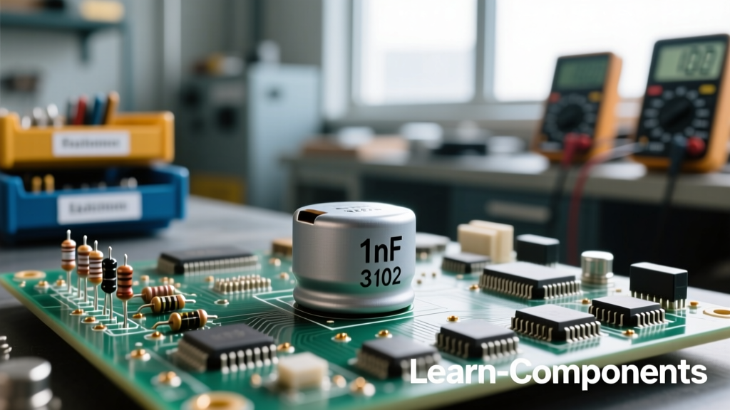
A 1nF capacitor is equivalent to 1000pF (picofarads) or 0.001µF (microfarads). On through-hole ceramic disc capacitors and some larger surface-mount devices (SMD), this is universally represented by the standard EIA 3-digit code: 102.
Decoding the 102 Marking
The 3-digit EIA system uses the first two digits as significant figures and the third digit as the multiplier (number of zeros). Therefore, 10 followed by two zeros equals 1000pF, which translates to 1nF. You may also see the letter 'n' used as a decimal placeholder on older European schematics or specific film capacitors, printed as 1n0.
However, in modern high-density PCB assembly, a 0402 or 0201 MLCC (Multi-Layer Ceramic Capacitor) is simply too small to print the 1nf capacitor code on the body. In these cases, the physical component is unmarked, and identification relies entirely on the reel packaging, the BOM (Bill of Materials), and the manufacturer's datasheet.
Dissecting the Manufacturer Part Number (MPN)
When sourcing components from distributors like Mouser or Digi-Key, you aren't just searching for '1nF'. You are searching for a highly specific Manufacturer Part Number (MPN). Let us break down a real-world datasheet part number for a 1nF ceramic capacitor from KEMET: C0603C102J5GACTU.
MPN Breakdown: C0603C102J5GACTU
C = Ceramic Capacitor
0603 = EIA Case Size (0.06' x 0.03')
C = Specification/Series (Standard)
102 = The 1nf capacitor code (10 x 10^2 pF)
J = Tolerance (J = ±5%)
5 = Voltage Rating (5 = 50VDC)
G = Dielectric Material (G = C0G/NP0)
A = Failure Rate (A = N/A)
C = Termination Finish (C = 100% Matte Sn)
TU = Packaging (TU = 7-inch Reel)
Understanding this syntax is critical. If you blindly substitute a part with a different dielectric or voltage rating, your circuit may fail in the field. For a deep dive into MLCC manufacturing and part numbering, the KEMET MLCC Basics guide provides excellent foundational knowledge on how these layers are constructed.
Critical Datasheet Parameters: Dielectric Class
The most crucial decision when specifying a 1nF capacitor is the dielectric material. At the 1nF threshold, you sit exactly at the crossroads between Class 1 and Class 2 ceramics. Both are readily available, but their datasheet behaviors are radically different.
C0G (NP0) vs. X7R
Class 1 dielectrics, specifically C0G (often referred to as NP0), are formulated from paraelectric materials like titanium dioxide. They offer extreme stability. Class 2 dielectrics, like X7R, use barium titanate, which provides a much higher dielectric constant, allowing for smaller physical package sizes but introducing severe non-linearities.
| Parameter | C0G (Class 1) | X7R (Class 2) |
|---|---|---|
| Temperature Coefficient | 0 ± 30 ppm/°C | ± 15% over -55°C to +125°C |
| Voltage Coefficient | None (Linear) | High (Capacitance drops under DC bias) |
| Piezoelectric Effect | None | High (Generates acoustic noise/microphonics) |
| Typical 1nF Package | 0402 or 0603 | 0201 or 0402 |
| Best Application | RF filters, Audio, Precision timing | General decoupling, bulk bypass |
The Hidden Trap: DC Bias and Microphonics
Many junior engineers make the mistake of reading only the nominal 1nf capacitor code and ignoring the DC Bias curves in the datasheet. If you place a 1nF X7R capacitor rated at 50V into a circuit with a 40V DC bias, the barium titanate dielectric saturates. The actual capacitance in-circuit might plummet to 300pF or lower, effectively detuning your filter or causing a timing circuit to fail.
Conversely, C0G dielectrics do not suffer from DC bias capacitance loss. A 1nF C0G capacitor will remain exactly 1nF whether 0V or 50V is applied across it. For authoritative data on how ceramic formulations react to electrical stress, refer to the Murata Ceramic Capacitor technical hub, which provides extensive graphs on DC bias characteristics.
The Microphonics Problem in Audio and High-Gain Circuits
Another datasheet parameter rarely discussed in basic tutorials is the piezoelectric effect. Because X7R is ferroelectric, it exhibits piezoelectric properties. If your PCB experiences mechanical vibration, a 1nF X7R capacitor will physically deform and generate a parasitic voltage across its terminals, acting like a microphone. In high-gain transimpedance amplifiers or audiophile DAC outputs, this introduces audible noise. C0G is not piezoelectric. Therefore, for any 1nF capacitor placed in the signal path of an audio or precision analog circuit, the datasheet must specify a C0G/NP0 dielectric.
High-Frequency Metrics: ESR, ESL, and SRF
When using a 1nF capacitor for high-frequency decoupling (e.g., bypassing a 2.4GHz WiFi module or a high-speed op-amp), the nominal capacitance is only half the story. The datasheet's impedance and resonance graphs dictate real-world performance.
- ESL (Equivalent Series Inductance): Dictated by the physical package size and PCB vias. An 0402 package has lower ESL than an 0603, making it superior for high-frequency decoupling, even if both share the same 1nf capacitor code.
- ESR (Equivalent Series Resistance): Determines how effectively the capacitor can shunt high-frequency noise to ground and how much heat it will dissipate in RF applications.
- SRF (Self-Resonant Frequency): The frequency at which the capacitive reactance equals the inductive reactance. A 1nF capacitor in an 0402 package typically has an SRF around 150 MHz to 200 MHz. Above this frequency, the component behaves as an inductor, rendering it useless for bypassing higher harmonics.
Always check the S-parameter or Impedance vs. Frequency graph in the manufacturer's datasheet to ensure the SRF aligns with the noise frequency you are trying to suppress.
Failure Modes and PCB Layout Rules
Finally, a proper datasheet breakdown must address mechanical reliability. MLCCs are brittle. The most common failure mode for surface-mount ceramics is flex cracking. When a PCB bends (during depaneling, connector insertion, or thermal expansion), the solder joints pull on the ceramic body, causing a microscopic crack that eventually leads to a short circuit or an open circuit.
To mitigate this, datasheets often recommend specific PCB layout practices:
- Orientation: Place 1nF capacitors parallel to the direction of expected board flexion.
- Distance from Edges: Keep components away from V-scores and router paths where mechanical stress is highest.
- Soft Termination: If your application involves high thermal cycling or heavy vibration (e.g., automotive or aerospace), look for MPNs that feature 'Flex' or 'Soft' terminations. These incorporate a conductive epoxy layer between the ceramic and the solder pad, absorbing mechanical stress before it can crack the dielectric layers.
Summary Checklist for Procurement
Before finalizing your BOM for a 1nF capacitor, verify the following against the manufacturer datasheet:
- Confirm the 1nf capacitor code (102) matches the required tolerance (e.g., J for ±5%, K for ±10%).
- Check the DC Bias curve if using X7R in a circuit with high DC voltage.
- Verify the Dielectric Class (C0G for analog/RF, X7R for general digital decoupling).
- Review the SRF graph to ensure the component will function at your target noise frequency.
- Evaluate the need for Soft Termination based on your PCB's mechanical environment.
By moving beyond the basic 3-digit marking and deeply analyzing the manufacturer datasheet, you ensure that your 1nF capacitors perform reliably across temperature, voltage, and mechanical stress, elevating your design from a fragile prototype to a robust, production-ready product.