
The Anatomy of Potentiometer Resistance
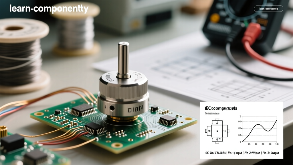
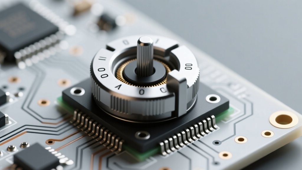
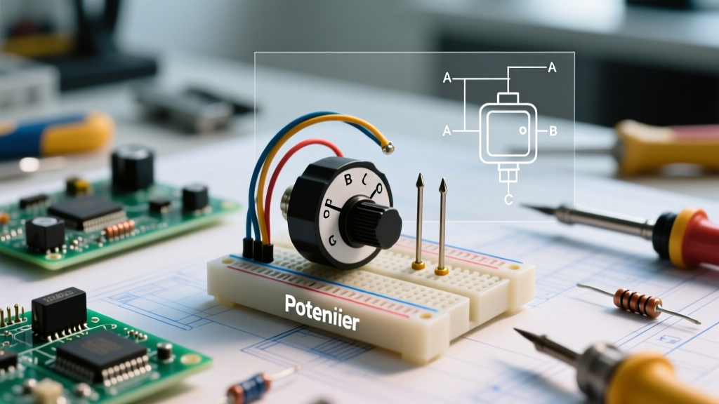
At its core, a potentiometer is a three-terminal resistor with a sliding or rotating contact that forms an adjustable voltage divider. However, performing an accurate potentiometer measurement requires more than just placing multimeter probes on two legs and reading the display. Whether you are debugging a vintage audio amplifier, calibrating a sensor interface, or prototyping a microcontroller input, understanding the physical and electrical nuances of the component is critical.
Potentiometers are defined by their total resistance, their taper (the relationship between mechanical position and resistance ratio), and their wiper contact resistance. According to All About Circuits, the most common beginner mistake is confusing the total end-to-end resistance with the variable wiper resistance, leading to incorrect biasing in transistor circuits or erratic ADC readings in microcontrollers.
Linear vs. Audio (Logarithmic) Taper Identification
Before integrating a pot into a circuit, you must verify its taper. The two most common tapers are Linear (B-taper) and Audio/Logarithmic (A-taper).
- Linear (B-Taper): The resistance changes at a constant rate. At exactly 50% mechanical rotation, the resistance between the wiper and either end terminal will be 50% of the total resistance.
- Audio (A-Taper): The resistance changes logarithmically to match human hearing perception. At 50% rotation, the resistance on one side will typically be around 10% to 15% of the total, while the other side will be 85% to 90%.
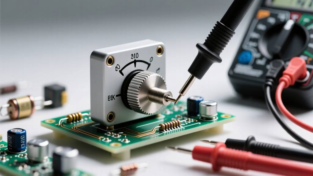
Measurement Protocol: Set your multimeter to the appropriate ohms range. Measure pins 1 and 3 to establish the baseline total resistance (e.g., 10kΩ). Then, rotate the shaft to the exact mechanical midpoint. Measure pin 1 to pin 2 (wiper). If you read ~5kΩ, it is linear. If you read ~1.5kΩ or ~8.5kΩ, it is an audio taper.
Bench Testing: Out-of-Circuit Measurement Protocol
When the component is isolated on your workbench, you have the opportunity to perform a comprehensive health check. This is the ideal time to test for wiper noise and track degradation.
Step-by-Step Multimeter Setup
For bench testing, digital multimeters (DMMs) like the Fluke 87V are excellent for static readings, but they can be frustrating for dynamic testing due to auto-ranging delays. As noted in Fluke's measurement guides, auto-ranging meters take a fraction of a second to lock onto a value. When sweeping a potentiometer, this delay masks micro-dropouts.
Pro-Tip: Switch your DMM to manual ranging. Select a range slightly higher than the pot's total resistance. Better yet, use an analog multimeter (like a classic Simpson 260) for the "sweep test." The physical inertia of the analog needle makes sudden resistance spikes (dropouts) instantly visible.
Verifying the Wiper Track Integrity
Connect your meter probes to the wiper (pin 2) and one of the end terminals (pin 1). Slowly rotate the shaft through its entire mechanical travel. The resistance should change smoothly. Any sudden jumps to infinity (open circuit) or erratic bouncing indicates a dirty carbon track or a worn wiper contact. In precision applications, even a 10-ohm bounce on a 10kΩ pot can introduce unacceptable noise into an op-amp feedback loop.
In-Circuit Potentiometer Measurement Challenges
Measuring a potentiometer while it is still soldered into a PCB is notoriously deceptive. The fundamental rule of resistance measurement is that the component must be isolated. When in-circuit, parallel pathways created by surrounding components (resistors, capacitors, semiconductor junctions) will skew your readings, almost always showing a lower resistance than the pot's actual value.
The Parallel Resistance Trap
Imagine you are measuring a 10kΩ volume potentiometer in an amplifier circuit. The wiper is connected to the grid of a vacuum tube or the high-impedance input of an op-amp, while the ends are tied to ground and the audio source. If you measure across the pot with your DMM, the meter's test current will flow through the parallel paths of the surrounding circuitry.
Expert Troubleshooting Rule: Never trust an in-circuit resistance measurement for a potentiometer. If you must verify the pot's value without desoldering it entirely, lift at least one end terminal (usually the ground or signal input leg) from the PCB pad to break the parallel circuit. Alternatively, power the circuit and measure the voltage at the wiper relative to ground while rotating the shaft to verify functional voltage division.
Application Configurations: Voltage Divider vs. Rheostat
How you wire the potentiometer dictates how you should measure and troubleshoot it. There are two primary configurations used in circuit design.
Data Table: Wiring & Measurement Expectations
| Configuration | Pins Used | Measurement Target | Common Failure Mode |
|---|---|---|---|
| Voltage Divider | Pins 1, 2, and 3 | Ratio of Vout to Vin based on wiper position. | Wiper noise causes voltage spikes; open track kills signal. |
| Rheostat (Variable Resistor) | Pins 1 and 2 (or 2 and 3) | Absolute resistance between wiper and one end. | Wiper lift-off causes infinite resistance (open circuit). |
| Rheostat (Fail-Safe) | Pins 1, 2, and 3 (Pin 3 tied to Pin 2) | Resistance drops to max value if wiper fails, rather than opening. | Mechanical binding prevents full range adjustment. |
In microcontroller prototyping, the voltage divider configuration is standard for reading user input via an ADC. In power electronics, the rheostat configuration is often used to set current limits or bias points. Tying the unused end terminal to the wiper (the fail-safe rheostat method) is a best practice in high-reliability designs to prevent a circuit from blowing up if the wiper loses contact.
Troubleshooting Common Potentiometer Failures
Even high-quality components from manufacturers like Bourns or Alps are subject to environmental degradation. Here is how to diagnose and resolve the most frequent issues.
Wiper Noise and Contact Resistance
Carbon track potentiometers are highly susceptible to oxidation and dust ingress. If your bench sweep test reveals erratic resistance, the track is likely dirty. The Fix: Avoid using standard WD-40 or isopropyl alcohol, which can leave residues or dry out the factory lubricants. Instead, use a specialized contact cleaner like DeoxIT D5. Apply a small burst into the casing slot, rotate the shaft back and forth 20 times to distribute the cleaner, and let it dry completely before re-measuring.
Temperature Coefficient (TCR) Impacts on Precision Trimpots
When working with multi-turn cermet trimpots (like the ubiquitous Bourns 3296W series), temperature plays a massive role in measurement accuracy. These components typically have a Temperature Coefficient of Resistance (TCR) of ±100 ppm/°C. If you are attempting a precise potentiometer measurement immediately after hand-soldering the component to the board, the residual heat will artificially inflate the resistance reading. Always allow precision trimpots to return to ambient room temperature (25°C) before performing final calibration measurements.
Mechanical Binding and Shaft Play
In panel-mount pots like the Alps RK27 series used in audiophile gear, mechanical wear can cause the shaft to wobble. This lateral play forces the wiper to ride unevenly on the carbon track, causing localized wear and eventual dead spots. If you measure a smooth electrical sweep but notice physical resistance or grinding when turning the knob, the internal bushing or conductive grease has failed. Electrical cleaning will not fix this; the component must be replaced or physically rebuilt.
Summary of Best Practices
Mastering potentiometer measurement is about understanding the context of the component. Always verify the taper before soldering, use manual-ranging or analog meters for dynamic wiper testing, and never trust in-circuit resistance readings without isolating the component. By applying these rigorous testing protocols, you will eliminate ghost faults and ensure reliable, noise-free circuit performance.