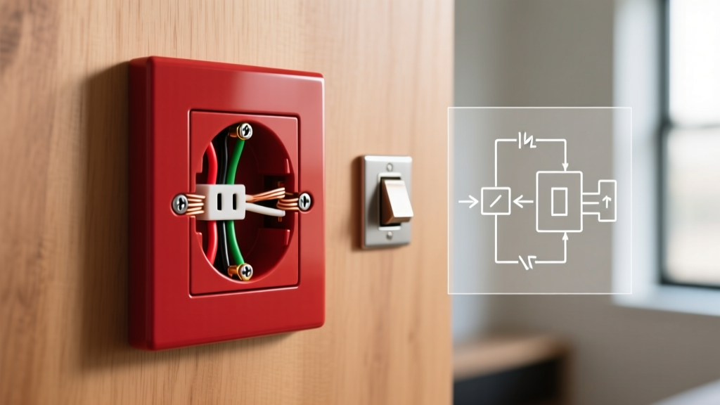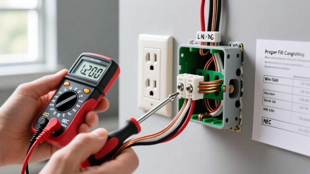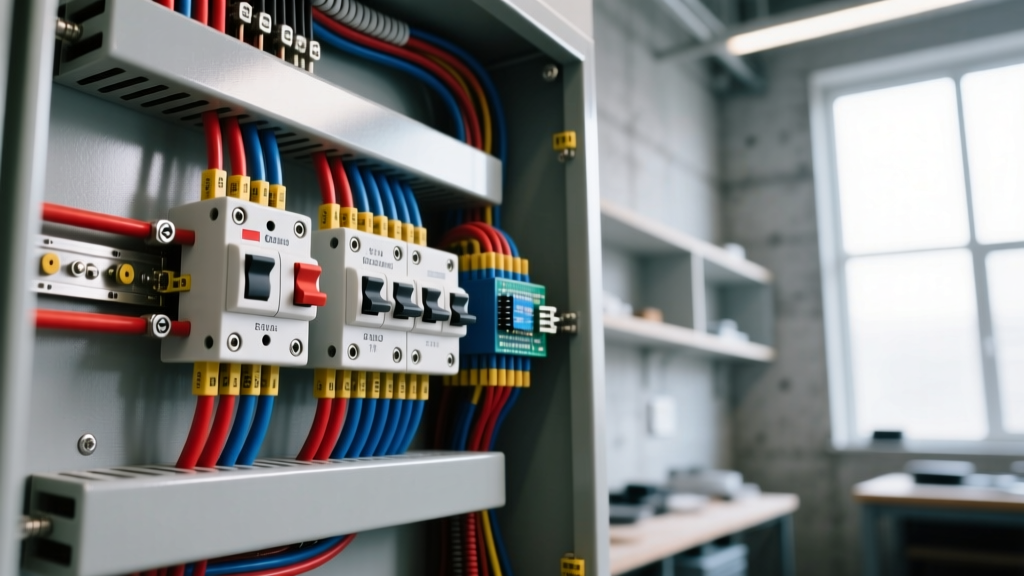

Wiring a panel box is the process of routing incoming feeder conductors to the main lugs or breaker, terminating branch circuits to their respective breakers, and correctly managing the neutral and ground bus bars to distribute power safely. What this changes in a real installation is the maximum continuous load capacity, the available fault current for breaker tripping, and the safety of the grounding path during a short circuit. What people most commonly confuse it with is the difference between the neutral bus bar and the equipment grounding bus bar, leading to dangerous and illegal bonding in subpanels.
The Core Concept: Main vs. Subpanel Architecture
When you are wiring a panel box, the first theoretical hurdle is understanding whether you are working on a Service Disconnect (Main Panel) or a Subpanel. The physical hardware might look identical—a steel enclosure with a main breaker and rows of branch breakers—but the internal wiring topology is fundamentally different.
In a Main Panel, the incoming utility lines (Line 1, Line 2, Neutral) land on the main breaker or main lugs. The neutral bus bar and the ground bus bar are physically connected by a main bonding jumper (often a green screw or a metal strap). This is the single point in the entire electrical system where neutral and ground are bonded, establishing the equipotential reference to earth.
In a Subpanel, the feeder arrives from a breaker in the main panel. Here, the neutral and ground bus bars must remain strictly isolated. If you wire a subpanel like a main panel and bond the neutral to the ground, you create a parallel path for normal return current to flow on the bare ground wires, which can energize appliance chassis and create shock hazards.
The Physics of the Bus Bars and Bonding
To understand why we separate the bars in a subpanel, you have to look at the physics of return current. In a 120V circuit, current flows out on the hot wire and returns on the neutral wire. The ground wire is a safety shield; it should only carry current during a fault (a short circuit).
If you bond neutral and ground at a subpanel, the return current reaches the subpanel's neutral bar and sees two paths back to the main panel: the insulated neutral wire and the bare ground wire. Because the ground wire is connected to the panel chassis, the metal enclosure itself becomes a current-carrying conductor. This is known as objectionable current (NEC Article 250.6). By keeping the bars isolated in a subpanel, normal return current is forced to use only the insulated neutral conductor, leaving the ground system at zero volts unless a fault occurs.
Worked Example: Sizing Feeder Conductors for a 125A Subpanel
Let’s apply theory to a real numeric scenario. You are wiring a panel box for a detached workshop subpanel. The subpanel has a 125A main breaker. The distance from the main panel to the subpanel is 150 feet. You want to use Aluminum SER (Service Entrance Rated) cable.
Step 1: Base Ampacity Sizing
According to NEC Table 310.16 (75°C column, as most panel lugs are rated for 75°C), a 125A load requires a conductor rated for at least 125A.
- 1 AWG Aluminum is rated for 130A. (Passes ampacity check).
- 2/0 AWG Aluminum is rated for 135A. (Passes ampacity check).
Step 2: Voltage Drop Calculation
NEC recommends keeping voltage drop under 3% for feeders (7.2V on a 240V system). We calculate using the formula: VD = (2 × K × I × D) / CM.
Assuming a continuous load of 100A (80% of the 125A breaker for worst-case continuous sizing), K=21.2 for Aluminum, and D=150 ft.
Testing 1 AWG Aluminum (Circular Mils = 83,690):
VD = (2 × 21.2 × 100 × 150) / 83,690 = 7.61 Volts.
Testing 2/0 AWG Aluminum (Circular Mils = 133,100):
VD = (2 × 21.2 × 100 × 150) / 133,100 = 4.77 Volts.
The Takeaway: Even though 1 AWG Aluminum can legally handle the 125A ampacity, wiring this panel box correctly requires upsizing to 2/0 AWG Aluminum to prevent voltage drop from starving heavy loads like welders or air compressors at the far end of the run.
Where You Meet This in Practice
You will encounter the theory of panel wiring and feeder sizing in several common residential and light-commercial scenarios:
- EV Charger Upgrades: Adding a 60A Level 2 EV charger often requires wiring a new subpanel or upgrading the main panel bus bar to handle the continuous 48A draw without violating the 80% NEC continuous load rule.
- Detached Workshops: Running a 4-wire feeder to a detached structure requires pulling a separate equipment grounding conductor and explicitly removing the green bonding screw in the destination panel.
- Solar Interconnections: Wiring a panel box for solar backfeeding requires placing the solar breaker at the absolute opposite end of the bus bar from the main breaker to satisfy the NEC 120% bus bar rule, preventing the bus bar stabs from overloading in the middle.
- Generator Interlocks: Installing a sliding plate interlock between the main breaker and a backfeed breaker requires strict adherence to torque specifications to ensure the lugs don't loosen from the vibration of the generator.
Decision Path: Selecting Your Panel Feeder and Bonding Setup
Use this decision tree to finalize your materials list when wiring a panel box for a subpanel feeder. Do not guess; follow the logic to the concrete pick.
| Scenario Constraint | If True... | If False... |
|---|---|---|
| Is the run under 50 feet? | Size wire purely by NEC 310.16 ampacity (75°C column). | Proceed to voltage drop calculation. |
| Is the calculated voltage drop > 3%? | Upsize conductor by one AWG step and recalculate. | Proceed to termination prep. |
| Are you using Aluminum conductors? | Apply Noalox (oxide inhibitor) and torque to exact in-lb spec. | Copper requires no oxide inhibitor, but still requires torque. |
| Is the destination panel a Subpanel? | Remove main bonding jumper; land neutral on isolated bar, ground on chassis bar. | Main Panel: Keep bonding jumper installed; land both on same bar if combined. |
Frequently Asked Questions
Do I really need a torque screwdriver for panel lugs?
Yes. As of NEC 2017 (110.14(D)), you must use a calibrated torque tool. Hand-tightening is a leading cause of thermal failures. For 2/0 Aluminum on a standard Square D or Eaton lug, the target is typically 40 to 45 inch-pounds. A loose lug creates high resistance, generating heat that will melt the breaker casing and cause a fire.
Can I double-tap a breaker in the main panel to feed a subpanel?
Only if the breaker is explicitly listed for two conductors. Look at the breaker's metal clamp plate; if it has a groove or indentation designed to hold two wires (common on some Square D QO and Eaton BR models up to 30A), it is legal. If the plate is flat, you must use a pigtail or a dedicated feed breaker. Never double-tap the main lugs.
What happens if I wire a 4-wire subpanel but only run 3 wires?
You will be forced to bond neutral and ground at the subpanel to complete the 120V circuit return path. This is a severe NEC violation for any new installation. It will cause objectionable current on your grounding system, potentially energizing the metal casing of your table saw or air compressor in the shop. Always run a 4-wire feeder (two hots, one neutral, one ground) for new subpanels.
For deeper reading on grounding and bonding physics, consult the NFPA 70 National Electrical Code Article 250, or review the training materials provided by the Electrical Training Alliance. Properly wiring a panel box is not just about making the power turn on; it is about engineering a predictable, low-impedance path for fault currents to ensure the breakers trip in milliseconds when things go wrong.