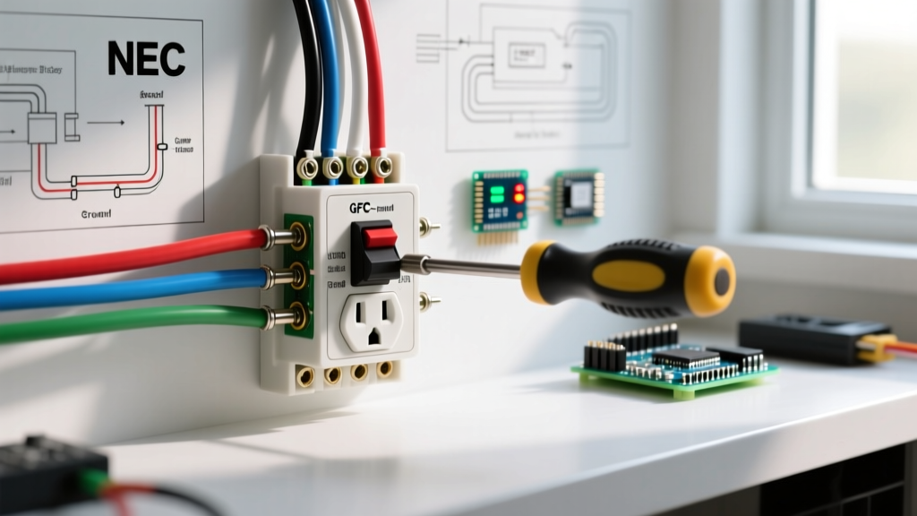
Replacing a standard duplex receptacle and single-pole switch with a single-gang combo device saves space and solves awkward wall box crowding. However, light switch outlet combo wiring introduces a unique set of terminal assignments and physical tab modifications that trip up even experienced DIYers. The direct answer for standard US NEC wiring is this: the bare or green ground wire lands on the green ground screw, the white neutral wire lands on the silver terminal, the black line (hot) wire lands on the brass LINE screw, and the black load (switch leg) wire lands on the brass LOAD screw. For a 15-amp branch circuit, use 14 AWG copper wire and a 15A/120V rated combo device; for a 20-amp circuit, use 12 AWG copper and a 20A rated device.
Terminal-to-Wire Mapping and Torque Specifications
Before stripping any wires, you need to understand exactly where each conductor terminates. Modern combo devices (like the Leviton 5243 or Eaton TR7745) feature distinct markings, but the brass screws can easily be confused if you do not check the LINE and LOAD stamps on the back of the yoke. The table below provides the definitive mapping, including the manufacturer-recommended torque specifications to prevent thermal loosening and arc faults.
| Terminal / Screw Color | Wire Color (US NEC) | Function & Circuit Role | Torque Spec (14-12 AWG) |
|---|---|---|---|
| Green Ground Screw | Bare Copper or Green | Equipment Grounding Conductor | 14 in-lbs (1.58 N-m) |
| Silver Terminal | White or Gray | Grounded Conductor (Neutral) | 14 in-lbs (1.58 N-m) |
| Brass Screw (Marked LINE) | Black or Red (Hot) | Ungrounded Conductor (Panel Feed) | 14 in-lbs (1.58 N-m) |
| Brass Screw (Marked LOAD) | Black or Red (Switched) | Ungrounded Conductor (Light Fixture Load) | 14 in-lbs (1.58 N-m) |
Note: If your combo device controls the receptacle itself rather than a separate light fixture, the LINE and LOAD brass screws will be bridged internally or require a specific pigtail configuration, which we cover in the split-receptacle section below.
Tools, Materials, and Device Ratings
Do not rely on a flathead screwdriver and a pair of dull pliers for this job. Proper wire preparation and termination are critical for preventing high-resistance connections that lead to melted yokes.
- Combo Device: Leviton 5243 (15A/125V) or 5245 (20A/125V) Tamper-Resistant (TR) combo switch/receptacle.
- Wire: 14 AWG solid copper (THHN or NM-B) for 15A circuits; 12 AWG solid copper for 20A circuits.
- Wire Strippers: Gauged strippers (e.g., Klein 11063W) to strip exactly 3/4 inch of insulation without nicking the copper.
- Torque Screwdriver: Calibrated to 14 in-lbs (e.g., Klein 690 or Wiha).
- Testers: Non-contact voltage tester (NCVT) and a True-RMS digital multimeter.
- Pigtails: 12 or 14 AWG solid copper pigtails with Wago 221 lever nuts if the box is crowded or multiple neutrals need joining.
Step-by-Step: Switch Controls Separate Light, Outlet Always Hot
This is the most common configuration: the switch operates an overhead light or fan, while the receptacle remains constantly powered for lamps or vacuum cleaners. We assume a single 120V feed entering the box, with a 2-wire switch leg exiting to the light.
- Prepare the Conductors: Strip exactly 3/4 inch of insulation from the black, white, and bare ground wires. Do not strip more, or you will expose bare copper outside the terminal saddle, creating a shock hazard.
- Terminate the Ground: Form a J-hook in the bare copper ground wire and loop it clockwise around the green ground screw on the combo device. Tighten to 14 in-lbs. If there are multiple ground wires in the box, bond them together with a pigtail first.
- Terminate the Neutral: Connect the white neutral wire from the panel feed to the silver terminal on the receptacle side of the combo device. If the white wire from the switch leg (light fixture) is also in the box, join the panel neutral, the light neutral, and a white pigtail using a Wago lever nut, then land the pigtail on the silver screw.
- Terminate the LINE (Hot Feed): Identify the black wire bringing constant power from the breaker panel. Land this black wire on the brass screw clearly marked 'LINE' on the back of the device yoke.
- Terminate the LOAD (Switch Leg): Take the black wire leading up to the light fixture. Land this black wire on the brass screw marked 'LOAD'.
- Fold and Secure: Carefully fold the wires into the back of the box, keeping the ground wire pushed to the rear. Mount the device using the provided 6-32 machine screws, ensuring the yoke sits flush against the drywall without bowing.
The Split Receptacle Variant (Half-Switched Outlet)
Sometimes, the switch is meant to control the bottom half of the receptacle (for a living room lamp), while the top half remains always hot. This requires a physical modification to the device that is entirely unique to combo and duplex receptacles.
Look at the brass (hot) side of the combo device. You will see a small metal fin connecting the LINE and LOAD brass terminals. You must break this brass fin using a pair of lineman pliers. Bend it back and forth until it snaps off. This electrically isolates the receptacle's hot bus from the switch's hot bus.
Once the brass fin is removed, you will wire the black panel feed to the brass LINE screw (powering the always-hot top half), and you will run a black pigtail from the brass LOAD screw to the brass receptacle terminal (powering the switched bottom half). The white neutral remains uninterrupted on the silver terminal.
Verify, Test, and the Most Common Botch
Before pushing the device fully into the box and screwing on the wall plate, you must verify your work. Turn the breaker back on at the panel.
Expected Multimeter Readings
- Hot to Neutral (LINE brass to Silver): 120V AC (acceptable range 114V - 126V).
- Hot to Ground (LINE brass to Green screw): 120V AC.
- Neutral to Ground (Silver to Green screw): Less than 1.0V AC (ideally 0.0V).
- Switch Continuity (LOAD brass to Ground with switch ON): 120V AC.
Plug a receptacle tester into the outlet. You should see two yellow lights indicating 'Correct Wiring'. Toggle the switch; if wired for a separate light, the tester lights should not change. If wired for a split receptacle, the tester should show power on the top half regardless of switch position, and power on the bottom half only when the switch is ON.
The Most Common Botch: The Neutral Fin Mistake
The single most destructive mistake in light switch outlet combo wiring is accidentally breaking the silver neutral fin instead of (or in addition to) the brass hot fin. If you break the silver fin, the neutral path to the top or bottom half of the receptacle is severed. The symptom is a receptacle that tests 'Open Neutral' on a plug-in tester, or a lamp that flickers and dims when a high-draw appliance is turned on elsewhere in the house.
An even more dangerous variation of this botch occurs on Multi-Wire Branch Circuits (MWBCs), where the box is fed by two hot legs sharing a single neutral. If you break the silver neutral fin on an MWBC and the two hots are on different phases, you can create a dead short or overload the shared neutral, risking an electrical fire. According to NFPA 70 (NEC) Article 210.4, MWBCs require simultaneous disconnecting, and splitting the neutral on a combo device without verifying the circuit topology is a severe code violation. Always leave the silver neutral fin intact unless you have explicitly verified a dedicated neutral for each receptacle half, which is exceedingly rare in standard residential combo installs.
By following the terminal mappings, respecting the torque specs, and double-checking which physical fin you are snapping, your combo device will provide years of safe, code-compliant service. For further reading on DIY electrical safety practices, consult the guidelines published by the Electrical Safety Foundation International (ESFI) before tackling any panel-adjacent work.