A three phase change over switch built from electromechanical contactors is the backbone of automatic transfer switches (ATS) and motor reversing circuits. Unlike a simple manual rotary cam switch, a contactor-based changeover system allows for remote, automated, or PLC-controlled switching between two 3-phase sources (e.g., utility grid and backup generator) or reversing the phase sequence for motor direction control. The direct answer to sizing this assembly is that your contactor’s AC-3 (motor) or AC-1 (resistive) utilization category governs the selection, not the raw thermal current rating printed on the side of the housing.
Below is the bench-to-jobsite guide for specifying, wiring, and testing a 3-phase electromechanical changeover assembly, based on IEC 60947-4-1 and NEC-style wiring practices.
Spec-Sheet Breakdown: Which Rating Column Governs Your Load?
The most common mistake when spec'ing a three phase change over switch is looking at the maximum continuous thermal current (Ith) and assuming it applies to all loads. It does not. Breaking a highly inductive 3-phase motor circuit generates an arc that is significantly harder to extinguish than breaking a resistive heating element. Therefore, the utilization category dictates the true working capacity of the contacts.
| Utilization Category | Application Type | Nominal Coil Voltage | Contact Rating (400V) | Breaking Capacity | Governing Rule |
|---|---|---|---|---|---|
| AC-1 | Resistive (Heaters, Lighting) | 24VDC / 120VAC | 40A | 1.5x Ie | Governs non-inductive loads; power factor > 0.95. |
| AC-3 | Squirrel Cage Motors (DOL) | 24VDC / 120VAC | 18A (approx. 7.5 kW) | 8x Ie (Starting) | Governs standard motor starting and running. |
| AC-4 | Plugging, Jogging, Reversing | 24VDC / 120VAC | 12A (approx. 4 kW) | 10x Ie (Plugging) | Governs rapid reversing changeover applications. |
| AC-15 | Control Circuits / Interlocks | 24VDC / 120VAC | 3A (Aux contacts) | N/A | Governs auxiliary contacts used for electrical interlocking. |
Source reference: IEC Utilization Categories for Contactors (Electrical Engineering Portal)
Which column governs? If your three phase change over switch is switching a 400V, 5.5 kW (7.5 HP) conveyor motor, you must look at the AC-3 column. A contactor rated for 40A under AC-1 might only be rated for 18A under AC-3. Sizing by the AC-1 column for a motor load will result in welded contacts during the first locked-rotor start event.
Coil vs. Contact Side Wiring & Interlocking Rules
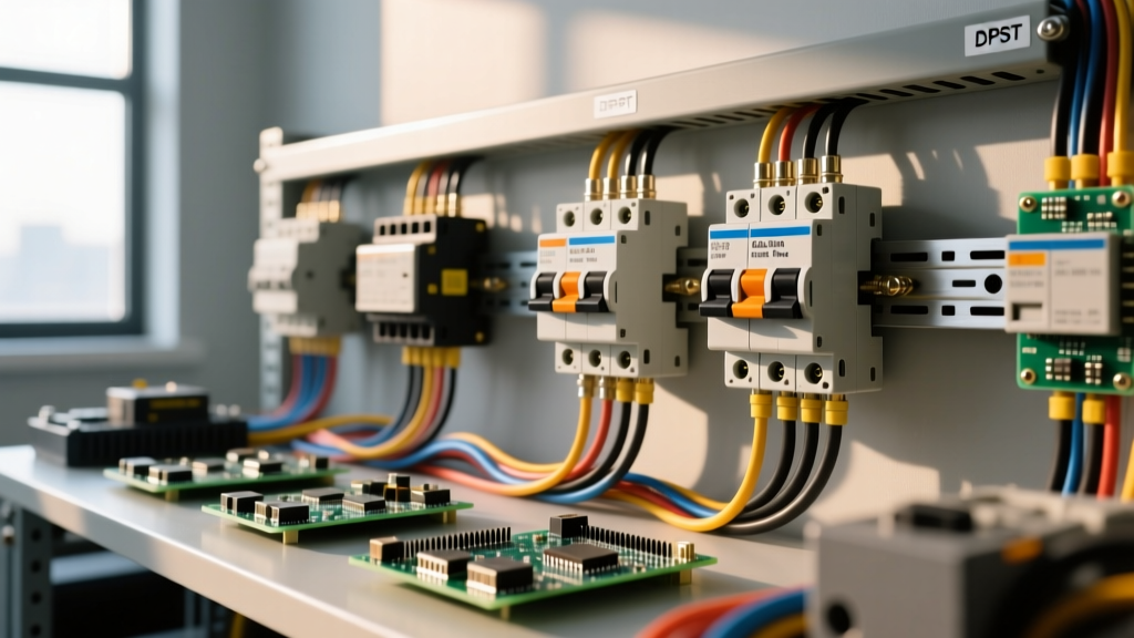
A changeover assembly requires two distinct 3-pole contactors. Wiring is split into the high-current contact side (power) and the low-current coil side (control).
The Contact Side (Power Circuit)
- Source A (e.g., Grid): Wire L1, L2, L3 to the top terminals (1/L1, 3/L2, 5/L3) of Contactor 1.
- Source B (e.g., Generator): Wire L1, L2, L3 to the top terminals of Contactor 2.
- Load Side: The bottom terminals (2/T1, 4/T2, 6/T3) of both contactors must be jumpered together using appropriately sized copper busbars or THHN wire, feeding the final load.
- Torque: Torque all power terminals to the manufacturer's spec (typically 2.5 Nm to 3.5 Nm for 10 AWG / 4mm² wire). Loose connections on the load-side jumper will cause uneven current sharing and thermal runaway.
The Coil Side (Control Circuit)
The coil terminals (A1 and A2) actuate the electromagnet. When wiring the control circuit for a three phase change over switch, pay strict attention to the coil voltage type:
- AC Coils (e.g., 120VAC, 240VAC): Wire directly to the control relays. The AC zero-crossing naturally helps extinguish the inductive kickback when the coil de-energizes.
- DC Coils (e.g., 24VDC): If your control circuit uses a 24VDC coil driven by a PLC transistor output, you must wire a flyback diode (e.g., 1N4007) in reverse parallel across A1 and A2. Without this diode, the inductive voltage spike (often exceeding 100V) when the coil drops out will instantly destroy the PLC's output transistor.
Selection Decision Path by Load Type
Use the following decision tree to select the correct contactor rating and interlocking strategy based on the specific load your three phase change over switch will manage.
| Load Type | Starting Current Multiplier | Required Category | Contactor Sizing & Interlock Rule |
|---|---|---|---|
| Resistive (Industrial Heaters) | 1.0x (No inrush) | AC-1 | Size to 100% of running current. Standard electrical interlock is sufficient. |
| Inductive (Transformers) | 8x to 12x (Magnetizing inrush) | AC-6a | Size contactor for 12x inrush making capacity. Add time-delay relay to prevent rapid changeover. |
| Squirrel Cage Motor (Pumps, Fans) | 6x to 8x (Locked rotor) | AC-3 | Size to AC-3 kW/HP rating. Mandatory mechanical + electrical interlock. |
| High-Inertia Motor (Crushers, Hoists) | 10x+ (Plugging/Reversing) | AC-4 | Size to AC-4 rating (usually 1-2 frame sizes larger than AC-3). Use zero-speed switch before changeover. |
Testing Dead and Live: When to Repair vs. Replace
Electromechanical contactors in a changeover assembly wear out. The silver-alloy contacts pit, and the mechanical interlocks degrade. Here is how to test the assembly and decide its fate.
Dead Testing (Power Off, Locked Out)
- Coil Continuity: Set your multimeter to the 200Ω range. Probe A1 and A2. A healthy 24VDC coil will read between 10Ω and 50Ω. An open reading (OL) means a burnt coil; replace the contactor.
- Contact Resistance: Manually press the contactor armature down with an insulated tool to close the main contacts. Measure across L1 to T1. You should read less than 0.5 milliohms. If it reads higher, the contacts are pitted or carbon-fouled.
- Insulation Resistance: Use a Megger (insulation resistance tester) at 500V DC between the power terminals and the contactor's grounded metal mounting plate. The reading must be >10 MΩ. Anything lower indicates internal carbon tracking or moisture ingress.
Live Testing (Under Load)
- Coil Voltage Check: Measure voltage across A1 and A2 while energized. It must remain within 85% to 110% of the nominal coil voltage. A voltage drop below 85% will cause the contactor to chatter, rapidly destroying the contacts.
- Voltage Drop Across Contacts: With the motor running at full load, measure the AC voltage drop from L1 to T1 on each phase. A healthy contact will drop less than 50mV. If one phase drops 200mV while the others drop 20mV, that specific pole is failing and causing phase imbalance.
When to Repair vs. Replace
Repair (Clean and Tighten): If the contacts show minor surface discoloration (silver oxide is highly conductive and normal), simply wipe them with isopropyl alcohol and re-torque the terminals. If the coil is fine but the mechanical interlock block is cracked, you can replace just the interlock block.
Replace the Contactor: Never attempt to file down pitted contacts. Modern contacts are made of silver-tin oxide or silver-cadmium oxide; filing removes the protective oxide layer and exposes the softer base metal, leading to immediate welding on the next start. If you see physical pitting deeper than 1mm, melted plastic around the arc chutes, or if the coil shows thermal blistering, replace the entire contactor unit immediately.
For further reading on safe installation practices and grounding requirements for transfer equipment, always consult the latest NFPA 70 (National Electrical Code) Article 700 and 702, as local Authority Having Jurisdiction (AHJ) interpretations will govern your final installation sign-off.